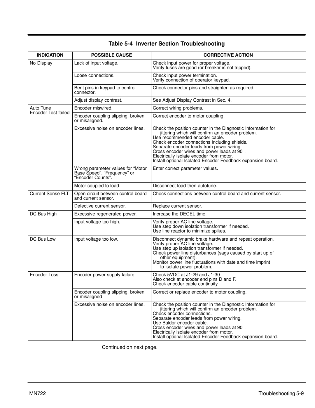
Table 5-4 Inverter Section Troubleshooting
INDICATION | POSSIBLE CAUSE | CORRECTIVE ACTION | |
|
|
| |
No Display | Lack of input voltage. | Check input power for proper voltage. | |
|
| Verify fuses are good (or breaker is not tripped). | |
|
|
| |
| Loose connections. | Check input power termination. | |
|
| Verify connection of operator keypad. | |
|
|
| |
| Bent pins in keypad to control | Check connector pins and straighten as required. | |
| connector. |
| |
|
|
| |
| Adjust display contrast. | See Adjust Display Contrast in Sec. 4. | |
|
|
| |
Auto Tune | Encoder miswired. | Correct wiring problems. | |
Encoder Test failed |
|
| |
Encoder coupling slipping, broken | Correct encoder to motor coupling. | ||
| |||
| or misaligned. |
| |
|
|
| |
| Excessive noise on encoder lines. | Check the position counter in the Diagnostic Information for | |
|
| jittering which will confirm an encoder problem. | |
|
| Use recommended encoder cable. | |
|
| Check encoder connections including shields. | |
|
| Separate encoder leads from power wiring. | |
|
| Cross encoder wires and power leads at 90° . | |
|
| Electrically isolate encoder from motor. | |
|
| Install optional Isolated Encoder Feedback expansion board. | |
|
|
| |
| Wrong parameter values for “Motor | Enter correct parameter values. | |
| Base Speed”, “Frequency” or |
| |
| “Encoder Counts”. |
| |
|
|
| |
| Motor coupled to load. | Disconnect load then autotune. | |
|
|
| |
Current Sense FLT | Open circuit between control board | Check connections between control board and current sensor. | |
| and current sensor. |
| |
|
|
| |
| Defective current sensor. | Replace current sensor. | |
|
|
| |
DC Bus High | Excessive regenerated power. | Increase the DECEL time. | |
|
|
| |
| Input voltage too high. | Verify proper AC line voltage. | |
|
| Use step down isolation transformer if needed. | |
|
| Use line reactor to minimize spikes. | |
|
|
| |
DC Bus Low | Input voltage too low. | Disconnect dynamic brake hardware and repeat operation. | |
|
| Verify proper AC line voltage. | |
|
| Use step up isolation transformer if needed. | |
|
| Check power line disturbances (sags caused by start up of | |
|
| other equipment). | |
|
| Monitor power line fluctuations with date and time imprint | |
|
| to isolate power problem. | |
|
|
| |
Encoder Loss | Encoder power supply failure. | Check 5VDC at | |
|
| Also check at encoder end pins D and F. | |
|
| Check encoder cable continuity. | |
|
|
| |
| Encoder coupling slipping, broken | Correct or replace encoder to motor coupling. | |
| or misaligned |
| |
|
|
| |
| Excessive noise on encoder lines. | Check the position counter in the Diagnostic Information for | |
|
| jittering which will confirm an encoder problem. | |
|
| Check encoder connections. | |
|
| Separate encoder leads from power wiring. | |
|
| Use Baldor encoder cable. | |
|
| Cross encoder wires and power leads at 90° . | |
|
| Electrically isolate encoder from motor. | |
|
| Install optional Isolated Encoder Feedback expansion board. | |
|
|
|
Continued on next page.
MN722 | Troubleshooting |
