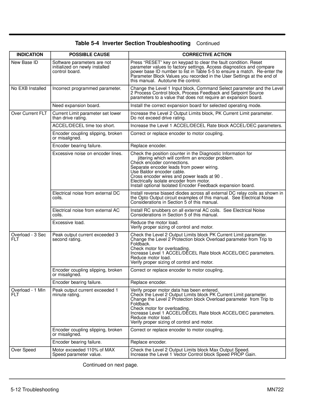
Table 5-4 Inverter Section Troubleshooting Continued
INDICATION | POSSIBLE CAUSE | CORRECTIVE ACTION |
|
|
|
New Base ID | Software parameters are not | Press “RESET” key on keypad to clear the fault condition. Reset |
| initialized on newly installed | parameter values to factory settings. Access diagnostics and compare |
| control board. | power base ID number to list in Table |
|
| Parameter Block Values you recorded in the User Settings at the end of |
|
| this manual. Autotune the control. |
|
|
|
No EXB Installed | Incorrect programmed parameter. | Change the Level 1 Input block, Command Select parameter and the Level |
|
| 2 Process Control block, Process Feedback and Setpoint Source |
|
| parameters to a value that does not require an expansion board. |
|
|
|
| Need expansion board. | Install the correct expansion board for selected operating mode. |
|
|
|
Over Current FLT | Current Limit parameter set lower | Increase the Level 2 Output Limits block, PK Current Limit parameter. |
| than drive rating. | Do not exceed drive rating. |
|
|
|
| ACCEL/DECEL time too short. | Increase the Level 1 ACCEL/DECEL Rate block ACCEL/DEC parameters. |
|
|
|
| Encoder coupling slipping, broken | Correct or replace encoder to motor coupling. |
| or misaligned. |
|
|
|
|
| Encoder bearing failure. | Replace encoder. |
|
|
|
| Excessive noise on encoder lines. | Check the position counter in the Diagnostic Information for |
|
| jittering which will confirm an encoder problem. |
|
| Check encoder connections. |
|
| Separate encoder leads from power wiring. |
|
| Use Baldor encoder cable. |
|
| Cross encoder wires and power leads at 90° . |
|
| Electrically isolate encoder from motor. |
|
| Install optional Isolated Encoder Feedback expansion board. |
|
|
|
| Electrical noise from external DC | Install reverse biased diodes across all external DC relay coils as shown in |
| coils. | the Opto Output circuit examples of this manual. See Electrical Noise |
|
| Considerations in Section 5 of this manual. |
|
|
|
| Electrical noise from external AC | Install RC snubbers on all external AC coils. See Electrical Noise |
| coils. | Considerations in Section 5 of this manual. |
|
|
|
| Excessive load. | Reduce the motor load. |
|
| Verify proper sizing of control and motor. |
|
|
|
Overload - 3 Sec | Peak output current exceeded 3 | Check the Level 2 Output Limits block PK Current Limit parameter. |
FLT | second rating. | Change the Level 2 Protection block Overload parameter from Trip to |
|
| Foldback. |
|
| Check motor for overloading. |
|
| Increase Level 1 ACCEL/DECEL Rate block ACCEL/DEC parameters. |
|
| Reduce motor load. |
|
| Verify proper sizing of control and motor. |
|
|
|
| Encoder coupling slipping, broken | Correct or replace encoder to motor coupling. |
| or misaligned. |
|
|
|
|
| Encoder bearing failure. | Replace encoder. |
|
|
|
Overload - 1 Min | Peak output current exceeded 1 | Verify proper motor data has been entered. |
FLT | minute rating. | Check the Level 2 Output Limits block PK Current Limit parameter. |
|
| Change the Level 2 Protection block Overload parameter from Trip to |
|
| Foldback. |
|
| Check motor for overloading. |
|
| Increase Level 1 ACCEL/DECEL Rate block ACCEL/DEC parameters. |
|
| Reduce motor load. |
|
| Verify proper sizing of control and motor. |
|
|
|
| Encoder coupling slipping, broken | Correct or replace encoder to motor coupling. |
| or misaligned. |
|
|
|
|
| Encoder bearing failure. | Replace encoder. |
|
|
|
Over Speed | Motor exceeded 110% of MAX | Check the Level 2 Output Limits block Max Output Speed. |
| Speed parameter value. | Increase the Level 1 Vector Control block Speed PROP Gain. |
|
|
|
| Continued on next page. | |
|
|
|
| MN722 | |