Electronic Pot 2 Wire Operating Mode
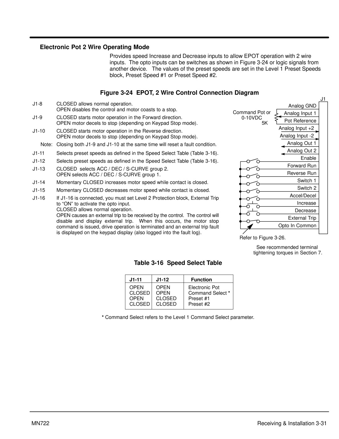
Provides speed Increase and Decrease inputs to allow EPOT operation with 2 wire inputs. The opto inputs can be switches as shown in Figure
Figure 3-24 EPOT, 2 Wire Control Connection Diagram
OPEN disables the control and motor coasts to a stop.
Note: Closing both
OPEN selects ACC / DEC /
CLOSED allows normal operation.
OPEN causes an external trip to be received by the control. The control will disable and display external trip. When this occurs, the motor stop command is issued, drive operation is terminated and an external trip fault is displayed on the keypad display (also logged into the fault log).
|
| J1 | |
| Analog GND | 1 | |
Command Pot or | Analog Input 1 | ||
2 | |||
Pot Reference | |||
5KW | 3 | ||
Analog Input +2 | |||
| 4 | ||
| Analog Input | ||
| 5 | ||
| Analog Out 1 | ||
| 6 | ||
| Analog Out 2 | ||
| 7 | ||
| Enable | ||
| 8 | ||
| Forward Run | ||
| 9 | ||
| Reverse Run | ||
| 10 | ||
| Switch 1 | 11 | |
| Switch 2 | 12 | |
| Accel/Decel | 13 | |
| Increase | 14 | |
| Decrease | 15 | |
| External Trip | 16 | |
| Opto In Common | 17 |
Refer to Figure
See recommended terminal tightening torques in Section 7.
Table 3-16 Speed Select Table
|
| Function |
OPEN | OPEN | Electronic Pot |
CLOSED | OPEN | Command Select * |
OPEN | CLOSED | Preset #1 |
CLOSED | CLOSED | Preset #2 |
|
|
|
*Command Select refers to the Level 1 Command Select parameter.
MN722 | Receiving & Installation |
