Figure 3-2 Configuring the Control Transformer for 380 - 400 VAC Installation
Contactor Transformer
Only size E and F controls require a change of the contactor transformer tap.
See Figure
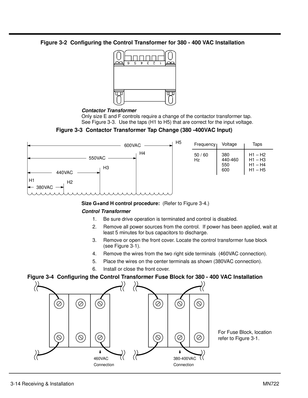
Figure 3-3 Contactor Transformer Tap Change (380 -400VAC Input)
|
|
|
|
|
|
|
| H5 | Frequency |
| Voltage |
| Taps |
|
|
|
|
| 600VAC |
|
|
| |||||
|
|
|
|
|
|
|
|
| |||||
|
|
|
|
|
|
| |||||||
|
|
|
|
|
|
|
|
|
|
|
|
|
|
|
|
|
|
|
| H4 |
|
|
|
|
|
| |
|
|
|
|
|
|
| 50 / 60 |
| 380 |
| H1 – H2 | ||
|
|
| 550VAC |
|
|
|
|
|
|
| |||
|
|
|
|
|
|
|
| Hz |
|
| H1 – H3 | ||
|
|
|
|
|
|
|
| ||||||
|
|
|
|
|
|
|
|
|
|
| |||
|
|
|
|
|
|
|
|
| |||||
|
|
| H3 |
|
|
| 550 |
| H1 – H4 | ||||
|
|
|
|
|
| 600 |
| H1 – H5 | |||||
| 440VAC |
|
|
|
|
|
|
|
|
|
| ||
|
|
|
|
|
|
|
|
|
|
|
|
| |
|
|
|
|
|
|
|
|
|
|
|
|
|
|
H1H2
380VAC
Size G+and H control procedure: (Refer to Figure 3-4.)
Control Transformer
1.Be sure drive operation is terminated and control is disabled.
2.Remove all power sources from the control. If power has been applied, wait at least 5 minutes for bus capacitors to discharge.
3.Remove or open the front cover. Locate the control transformer fuse block (see Figure
4.Remove the wires from the two right side terminals (460VAC connection).
5.Place the wires on the center terminals as shown (380VAC connection).
6.Install or close the front cover.
Figure 3-4 Configuring the Control Transformer Fuse Block for 380 - 400 VAC Installation
For Fuse Block, location refer to Figure
460VAC | |
Connection | Connection |
MN722 |