Standard Run 3 Wire Mode Connections

In Standard Run mode, the control is operated by the opto isolated inputs at J1-8 through J1-16 and the analog command input. The opto inputs can be switches as shown in Figure 3-18 or logic signals from another device. The external trip opto input at J1-16 is active if connected as shown and the Level 2 Protection block, External Trip parameter is set to ON.

For 4–20mA operation, refer to Table 3-10. Analog input 2 can then be used for 4–20mA operation.

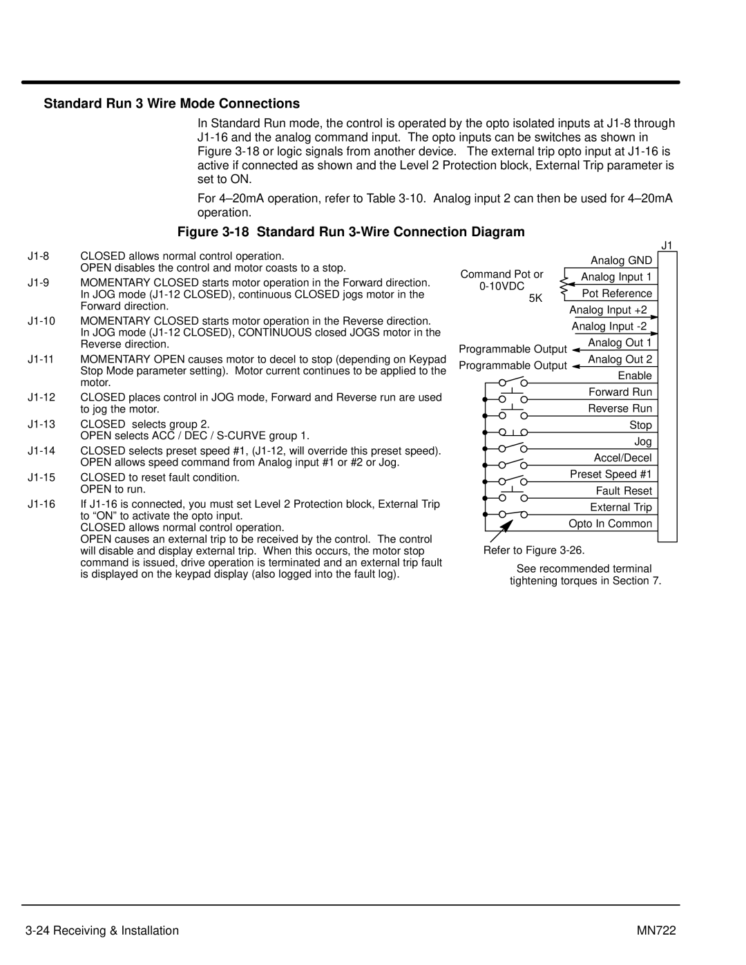
Figure 3-18 Standard Run 3-Wire Connection Diagram

J1-8 CLOSED allows normal control operation.

OPEN disables the control and motor coasts to a stop.

J1-9 MOMENTARY CLOSED starts motor operation in the Forward direction. In JOG mode (J1-12 CLOSED), continuous CLOSED jogs motor in the Forward direction.

J1-10 MOMENTARY CLOSED starts motor operation in the Reverse direction. In JOG mode (J1-12 CLOSED), CONTINUOUS closed JOGS motor in the Reverse direction.

J1-11 MOMENTARY OPEN causes motor to decel to stop (depending on Keypad Stop Mode parameter setting). Motor current continues to be applied to the motor.

J1-12 CLOSED places control in JOG mode, Forward and Reverse run are used to jog the motor.

J1-13 CLOSED selects group 2.

OPEN selects ACC / DEC / S-CURVE group 1.

J1-14 CLOSED selects preset speed #1, (J1-12, will override this preset speed). OPEN allows speed command from Analog input #1 or #2 or Jog.

J1-15 CLOSED to reset fault condition. OPEN to run.

J1-16 If J1-16 is connected, you must set Level 2 Protection block, External Trip to “ON” to activate the opto input.

CLOSED allows normal control operation.

OPEN causes an external trip to be received by the control. The control will disable and display external trip. When this occurs, the motor stop command is issued, drive operation is terminated and an external trip fault is displayed on the keypad display (also logged into the fault log).


J1


Analog GND

1

Command Pot or

Analog Input 1


0-10VDC

Pot Reference

2

5KW

3

Analog Input +2


4


Analog Input -2


5


Analog Out 1

Programmable Output

6

Analog Out 2

Programmable Output

7

Enable


8


Forward Run


9


Reverse Run


10


Stop

11


Jog


12


Accel/Decel

13


Preset Speed #1

14


Fault Reset

15


External Trip

16


Opto In Common

17

Refer to Figure 3-26.

See recommended terminal tightening torques in Section 7.

3-24 Receiving & Installation

MN722

Page 35
Image 35
Baldor mn722 manual Standard Run 3 Wire Mode Connections, 5KW