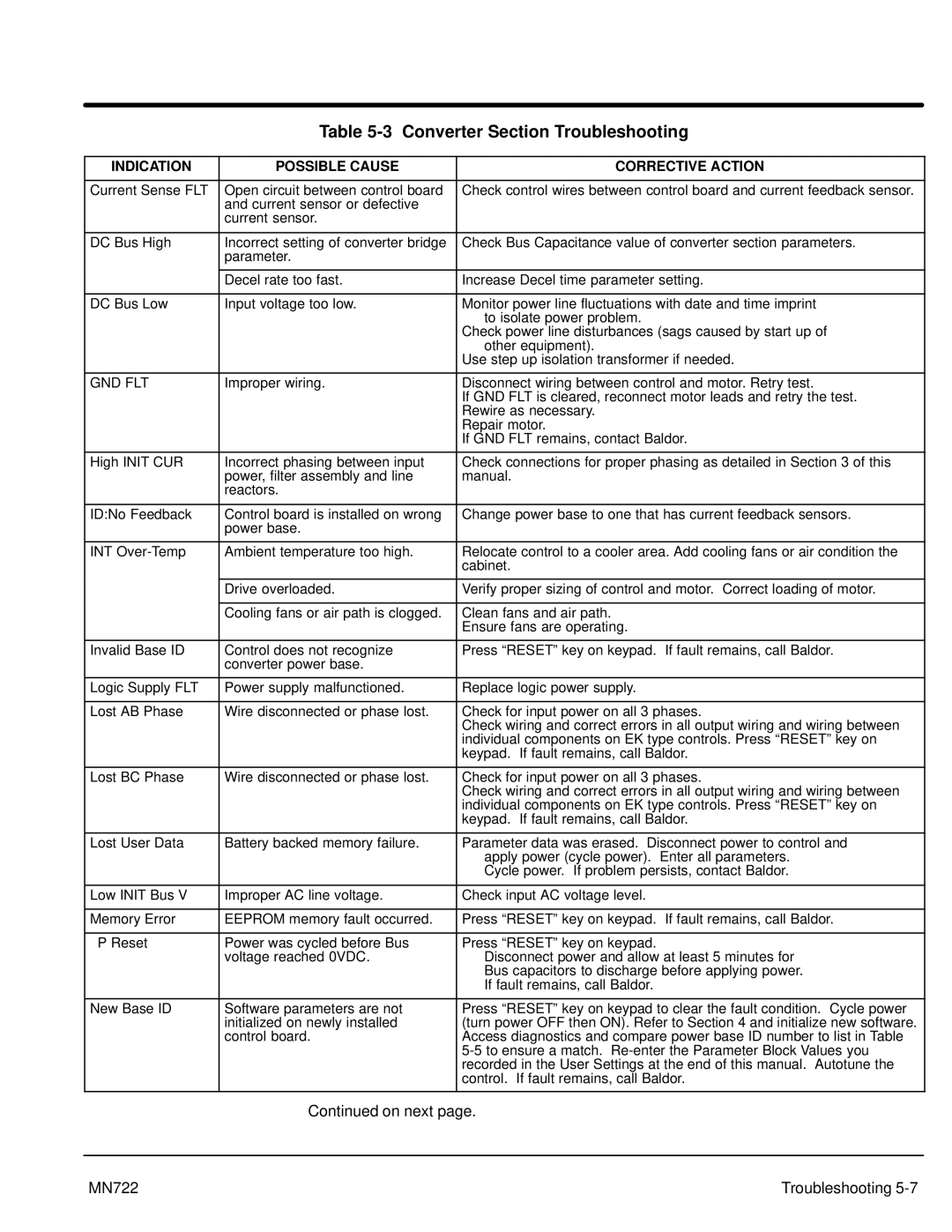
Table 5-3 Converter Section Troubleshooting
INDICATION | POSSIBLE CAUSE | CORRECTIVE ACTION |
|
|
|
Current Sense FLT | Open circuit between control board | Check control wires between control board and current feedback sensor. |
| and current sensor or defective |
|
| current sensor. |
|
|
|
|
DC Bus High | Incorrect setting of converter bridge | Check Bus Capacitance value of converter section parameters. |
| parameter. |
|
|
|
|
| Decel rate too fast. | Increase Decel time parameter setting. |
|
|
|
DC Bus Low | Input voltage too low. | Monitor power line fluctuations with date and time imprint |
|
| to isolate power problem. |
|
| Check power line disturbances (sags caused by start up of |
|
| other equipment). |
|
| Use step up isolation transformer if needed. |
|
|
|
GND FLT | Improper wiring. | Disconnect wiring between control and motor. Retry test. |
|
| If GND FLT is cleared, reconnect motor leads and retry the test. |
|
| Rewire as necessary. |
|
| Repair motor. |
|
| If GND FLT remains, contact Baldor. |
|
|
|
High INIT CUR | Incorrect phasing between input | Check connections for proper phasing as detailed in Section 3 of this |
| power, filter assembly and line | manual. |
| reactors. |
|
|
|
|
ID:No Feedback | Control board is installed on wrong | Change power base to one that has current feedback sensors. |
| power base. |
|
|
|
|
INT | Ambient temperature too high. | Relocate control to a cooler area. Add cooling fans or air condition the |
|
| cabinet. |
|
|
|
| Drive overloaded. | Verify proper sizing of control and motor. Correct loading of motor. |
|
|
|
| Cooling fans or air path is clogged. | Clean fans and air path. |
|
| Ensure fans are operating. |
|
|
|
Invalid Base ID | Control does not recognize | Press “RESET” key on keypad. If fault remains, call Baldor. |
| converter power base. |
|
|
|
|
Logic Supply FLT | Power supply malfunctioned. | Replace logic power supply. |
|
|
|
Lost AB Phase | Wire disconnected or phase lost. | Check for input power on all 3 phases. |
|
| Check wiring and correct errors in all output wiring and wiring between |
|
| individual components on EK type controls. Press “RESET” key on |
|
| keypad. If fault remains, call Baldor. |
|
|
|
Lost BC Phase | Wire disconnected or phase lost. | Check for input power on all 3 phases. |
|
| Check wiring and correct errors in all output wiring and wiring between |
|
| individual components on EK type controls. Press “RESET” key on |
|
| keypad. If fault remains, call Baldor. |
|
|
|
Lost User Data | Battery backed memory failure. | Parameter data was erased. Disconnect power to control and |
|
| apply power (cycle power). Enter all parameters. |
|
| Cycle power. If problem persists, contact Baldor. |
|
|
|
Low INIT Bus V | Improper AC line voltage. | Check input AC voltage level. |
|
|
|
Memory Error | EEPROM memory fault occurred. | Press “RESET” key on keypad. If fault remains, call Baldor. |
|
|
|
mP Reset | Power was cycled before Bus | Press “RESET” key on keypad. |
| voltage reached 0VDC. | Disconnect power and allow at least 5 minutes for |
|
| Bus capacitors to discharge before applying power. |
|
| If fault remains, call Baldor. |
|
|
|
New Base ID | Software parameters are not | Press “RESET” key on keypad to clear the fault condition. Cycle power |
| initialized on newly installed | (turn power OFF then ON). Refer to Section 4 and initialize new software. |
| control board. | Access diagnostics and compare power base ID number to list in Table |
|
| |
|
| recorded in the User Settings at the end of this manual. Autotune the |
|
| control. If fault remains, call Baldor. |
|
|
|
| Continued on next page. | |
|
|
|
MN722 |
| Troubleshooting |