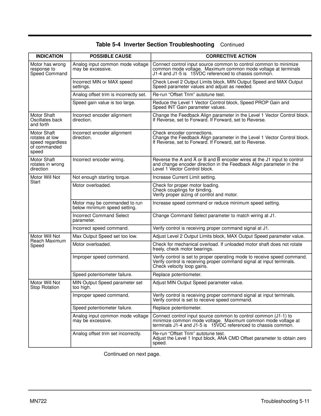
Table 5-4 Inverter Section Troubleshooting Continued
INDICATION | POSSIBLE CAUSE |
|
| CORRECTIVE ACTION | |||
|
|
|
|
|
|
| |
Motor has wrong | Analog input common mode voltage | Connect control input source common to control common to minimize | |||||
response to | may be excessive. | common mode voltage. Maximum common mode voltage at terminals | |||||
Speed Command |
| ||||||
|
|
|
|
|
|
| |
| Incorrect MIN or MAX speed | Check Level 2 Output Limits block, MIN Output Speed and MAX Output | |||||
| settings. | Speed parameter values and adjust as needed. | |||||
|
|
|
|
|
|
| |
| Analog offset trim is incorrectly set. | ||||||
|
|
|
|
|
|
| |
| Speed gain value is too large. | Reduce the Level 1 Vector Control block, Speed PROP Gain and | |||||
|
| Speed INT Gain parameter values. | |||||
|
|
|
|
|
|
| |
Motor Shaft | Incorrect encoder alignment | Change the Feedback Align parameter in the Level 1 Vector Control block. | |||||
Oscillates back | direction. | If Reverse, set to Forward. If Forward, set to Reverse. | |||||
and forth |
|
|
|
|
|
| |
|
|
|
|
|
|
| |
Motor Shaft | Incorrect encoder alignment | Check encoder connections. | |||||
rotates at low | direction. | Change the Feedback Align parameter in the Level 1 Vector Control block. | |||||
speed regardless |
| If Reverse, set to Forward. If Forward, set to Reverse. | |||||
of commanded |
|
|
|
|
|
| |
speed |
|
|
|
|
|
| |
|
|
|
|
|
|
| |
Motor Shaft | Incorrect encoder wiring. | Reverse the A and |
| or B and |
| encoder wires at the J1 input to control | |
A | B | ||||||
rotates in wrong |
| and change encoder direction in the Feedback Align parameter in the | |||||
direction |
| Level 1 Vector Control block. | |||||
|
|
| |||||
Motor Will Not | Not enough starting torque. | Increase Current Limit setting. | |||||
Start |
|
|
|
|
|
| |
Motor overloaded. | Check for proper motor loading. | ||||||
| |||||||
|
| Check couplings for binding. | |||||
|
| Verify proper sizing of control and motor. | |||||
|
|
| |||||
| Motor may be commanded to run | Increase speed command or reduce minimum speed setting. | |||||
| below minimum speed setting. |
|
|
|
|
| |
|
|
| |||||
| Incorrect Command Select | Change Command Select parameter to match wiring at J1. | |||||
| parameter. |
|
|
|
|
| |
|
|
| |||||
| Incorrect speed command. | Verify control is receiving proper command signal at J1. | |||||
|
|
| |||||
Motor Will Not | Max Output Speed set too low. | Adjust Level 2 Output Limits block, MAX Output Speed parameter value. | |||||
Reach Maximum |
|
|
|
|
|
| |
Motor overloaded. | Check for mechanical overload. If unloaded motor shaft does not rotate | ||||||
Speed | |||||||
|
| freely, check motor bearings. | |||||
|
|
| |||||
| Improper speed command. | Verify control is set to proper operating mode to receive speed command. | |||||
|
| Verify control is receiving proper command signal at input terminals. | |||||
|
| Check velocity loop gains. | |||||
|
|
| |||||
| Speed potentiometer failure. | Replace potentiometer. | |||||
|
|
| |||||
Motor Will Not | MIN Output Speed parameter set | Adjust MIN Output Speed parameter value. | |||||
Stop Rotation | too high. |
|
|
|
|
| |
|
|
| |||||
| Improper speed command. | Verify control is receiving proper command signal at input terminals. | |||||
|
| Verify control is set to receive speed command. | |||||
|
|
| |||||
| Speed potentiometer failure. | Replace potentiometer. | |||||
|
|
| |||||
| Analog input common mode voltage | Connect control input source common to control common | |||||
| may be excessive. | minimize common mode voltage. Maximum common mode voltage at | |||||
|
| terminals | |||||
|
|
| |||||
| Analog offset trim set incorrectly. | ||||||
|
| Adjust the Level 1 Input block, ANA CMD Offset parameter to obtain zero | |||||
|
| speed. | |||||
|
|
|
|
|
|
| |
Continued on next page.
MN722 | Troubleshooting |