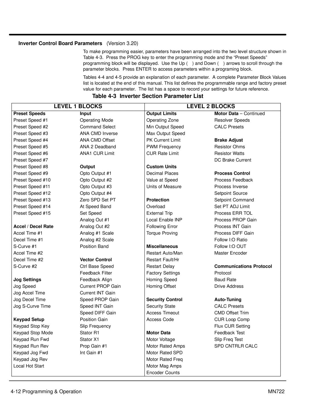
Inverter Control Board Parameters (Version 3.20)
To make programming easier, parameters have been arranged into the two level structure shown in Table
Tables
Table 4-3 Inverter Section Parameter List
|
| LEVEL 1 BLOCKS |
| LEVEL 2 BLOCKS |
|
| Preset Speeds | Input | Output Limits | Motor Data – Continued |
|
| Preset Speed #1 | Operating Mode | Operating Zone | Resolver Speeds |
|
| Preset Speed #2 | Command Select | Min Output Speed | CALC Presets |
|
| Preset Speed #3 | ANA CMD Inverse | Max Output Speed |
|
|
| Preset Speed #4 | ANA CMD Offset | PK Current Limit | Brake Adjust |
|
| Preset Speed #5 | ANA 2 Deadband | PWM Frequency | Resistor Ohms |
|
| Preset Speed #6 | ANA1 CUR Limit | CUR Rate Limit | Resistor Watts |
|
| Preset Speed #7 |
|
| DC Brake Current |
|
| Preset Speed #8 | Output | Custom Units |
|
|
| Preset Speed #9 | Opto Output #1 | Decimal Places | Process Control |
|
| Preset Speed #10 | Opto Output #2 | Value at Speed | Process Feedback |
|
| Preset Speed #11 | Opto Output #3 | Units of Measure | Process Inverse |
|
| Preset Speed #12 | Opto Output #4 |
| Setpoint Source |
|
| Preset Speed #13 | Zero SPD Set PT | Protection | Setpoint Command |
|
| Preset Speed #14 | At Speed Band | Overload | Set PT ADJ Limit |
|
| Preset Speed #15 | Set Speed | External Trip | Process ERR TOL |
|
|
| Analog Out #1 | Local Enable INP | Process PROP Gain |
|
| Accel / Decel Rate | Analog Out #2 | Following Error | Process INT Gain |
|
| Accel Time #1 | Analog #1 Scale | Torque Proving | Process DIFF Gain |
|
| Decel Time #1 | Analog #2 Scale |
| Follow I:O Ratio |
|
| Position Band | Miscellaneous | Follow I:O OUT |
| |
| Accel Time #2 |
| Restart Auto/Man | Master Encoder |
|
| Decel Time #2 | Vector Control | Restart Fault/Hr |
|
|
| Ctrl Base Speed | Restart Delay | Communications Protocol |
| |
|
| Feedback Filter | Factory Settings | Protocol |
|
| Jog Settings | Feedback Align | Homing Speed | Baud Rate |
|
| Jog Speed | Current PROP Gain | Homing Offset | Drive Address |
|
| Jog Accel Time | Current INT Gain |
|
|
|
| Jog Decel Time | Speed PROP Gain | Security Control |
|
|
| Jog | Speed INT Gain | Security State | CALC Presets |
|
|
| Speed DIFF Gain | Access Timeout | CMD Offset Trim |
|
| Keypad Setup | Position Gain | Access Code | CUR Loop Comp |
|
| Keypad Stop Key | Slip Frequency |
| Flux CUR Setting |
|
| Keypad Stop Mode | Stator R1 | Motor Data | Feedback Test |
|
| Keypad Run Fwd | Stator X1 | Motor Voltage | Slip Freq Test |
|
| Keypad Run Rev | Prop Gain #1 | Motor Rated Amps | SPD CNTRLR CALC |
|
| Keypad Jog Fwd | Int Gain #1 | Motor Rated SPD |
|
|
| Keypad Jog Rev |
| Motor Rated Freq |
|
|
| Local Hot Start |
| Motor Mag Amps |
|
|
|
|
| Encoder Counts |
|
|
|
|
|
|
|
|
|
|
|
|
|
|
MN722 |