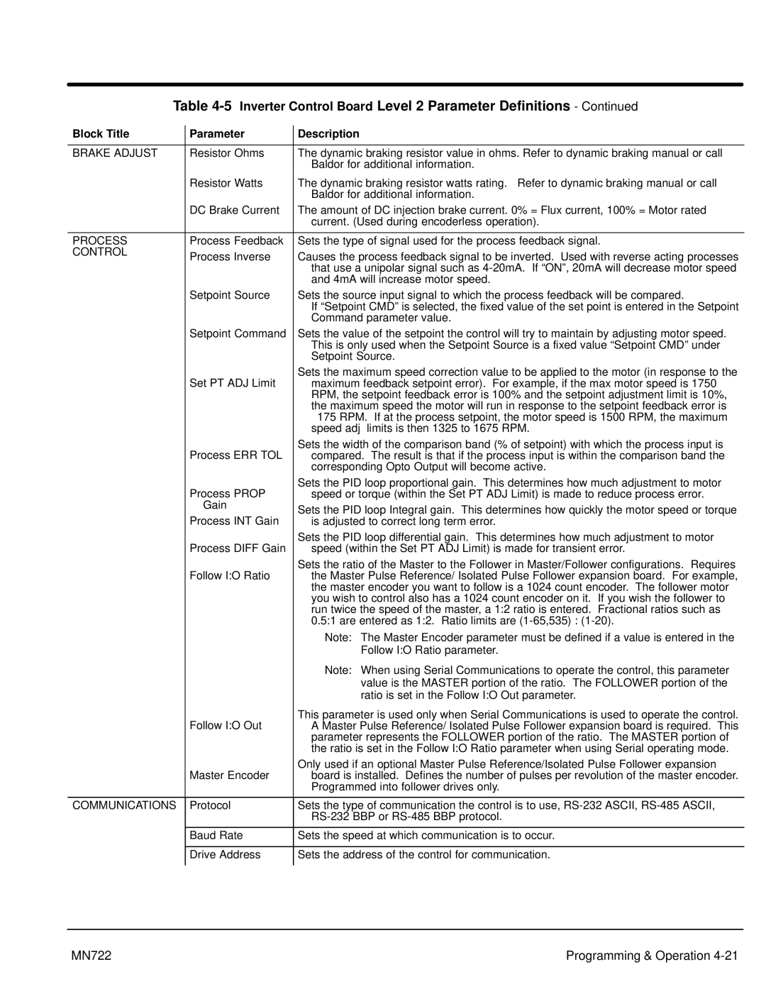
Table 4-5 Inverter Control Board Level 2 Parameter Definitions - Continued
Block Title | Parameter | Description |
|
|
|
BRAKE ADJUST | Resistor Ohms | The dynamic braking resistor value in ohms. Refer to dynamic braking manual or call |
|
| Baldor for additional information. |
| Resistor Watts | The dynamic braking resistor watts rating. Refer to dynamic braking manual or call |
|
| Baldor for additional information. |
| DC Brake Current | The amount of DC injection brake current. 0% = Flux current, 100% = Motor rated |
|
| current. (Used during encoderless operation). |
|
|
|
PROCESS | Process Feedback | Sets the type of signal used for the process feedback signal. |
CONTROL | Process Inverse | Causes the process feedback signal to be inverted. Used with reverse acting processes |
| ||
|
| that use a unipolar signal such as |
|
| and 4mA will increase motor speed. |
| Setpoint Source | Sets the source input signal to which the process feedback will be compared. |
|
| If “Setpoint CMD” is selected, the fixed value of the set point is entered in the Setpoint |
|
| Command parameter value. |
| Setpoint Command | Sets the value of the setpoint the control will try to maintain by adjusting motor speed. |
|
| This is only used when the Setpoint Source is a fixed value “Setpoint CMD” under |
|
| Setpoint Source. |
| Set PT ADJ Limit | Sets the maximum speed correction value to be applied to the motor (in response to the |
| maximum feedback setpoint error). For example, if the max motor speed is 1750 | |
|
| RPM, the setpoint feedback error is 100% and the setpoint adjustment limit is 10%, |
|
| the maximum speed the motor will run in response to the setpoint feedback error is |
|
| ± 175 RPM. If at the process setpoint, the motor speed is 1500 RPM, the maximum |
|
| speed adj limits is then 1325 to 1675 RPM. |
| Process ERR TOL | Sets the width of the comparison band (% of setpoint) with which the process input is |
| compared. The result is that if the process input is within the comparison band the | |
|
| corresponding Opto Output will become active. |
| Process PROP | Sets the PID loop proportional gain. This determines how much adjustment to motor |
| speed or torque (within the Set PT ADJ Limit) is made to reduce process error. | |
| Gain | Sets the PID loop Integral gain. This determines how quickly the motor speed or torque |
| Process INT Gain | |
| is adjusted to correct long term error. | |
| Process DIFF Gain | Sets the PID loop differential gain. This determines how much adjustment to motor |
| speed (within the Set PT ADJ Limit) is made for transient error. | |
| Follow I:O Ratio | Sets the ratio of the Master to the Follower in Master/Follower configurations. Requires |
| the Master Pulse Reference/ Isolated Pulse Follower expansion board. For example, | |
|
| the master encoder you want to follow is a 1024 count encoder. The follower motor |
|
| you wish to control also has a 1024 count encoder on it. If you wish the follower to |
|
| run twice the speed of the master, a 1:2 ratio is entered. Fractional ratios such as |
|
| 0.5:1 are entered as 1:2. Ratio limits are |
|
| Note: The Master Encoder parameter must be defined if a value is entered in the |
|
| Follow I:O Ratio parameter. |
|
| Note: When using Serial Communications to operate the control, this parameter |
|
| value is the MASTER portion of the ratio. The FOLLOWER portion of the |
|
| ratio is set in the Follow I:O Out parameter. |
| Follow I:O Out | This parameter is used only when Serial Communications is used to operate the control. |
| A Master Pulse Reference/ Isolated Pulse Follower expansion board is required. This | |
|
| parameter represents the FOLLOWER portion of the ratio. The MASTER portion of |
|
| the ratio is set in the Follow I:O Ratio parameter when using Serial operating mode. |
| Master Encoder | Only used if an optional Master Pulse Reference/Isolated Pulse Follower expansion |
| board is installed. Defines the number of pulses per revolution of the master encoder. | |
|
| Programmed into follower drives only. |
|
|
|
COMMUNICATIONS
Protocol | Sets the type of communication the control is to use, |
| |
|
|
Baud Rate | Sets the speed at which communication is to occur. |
|
|
Drive Address | Sets the address of the control for communication. |
MN722 | Programming & Operation |
