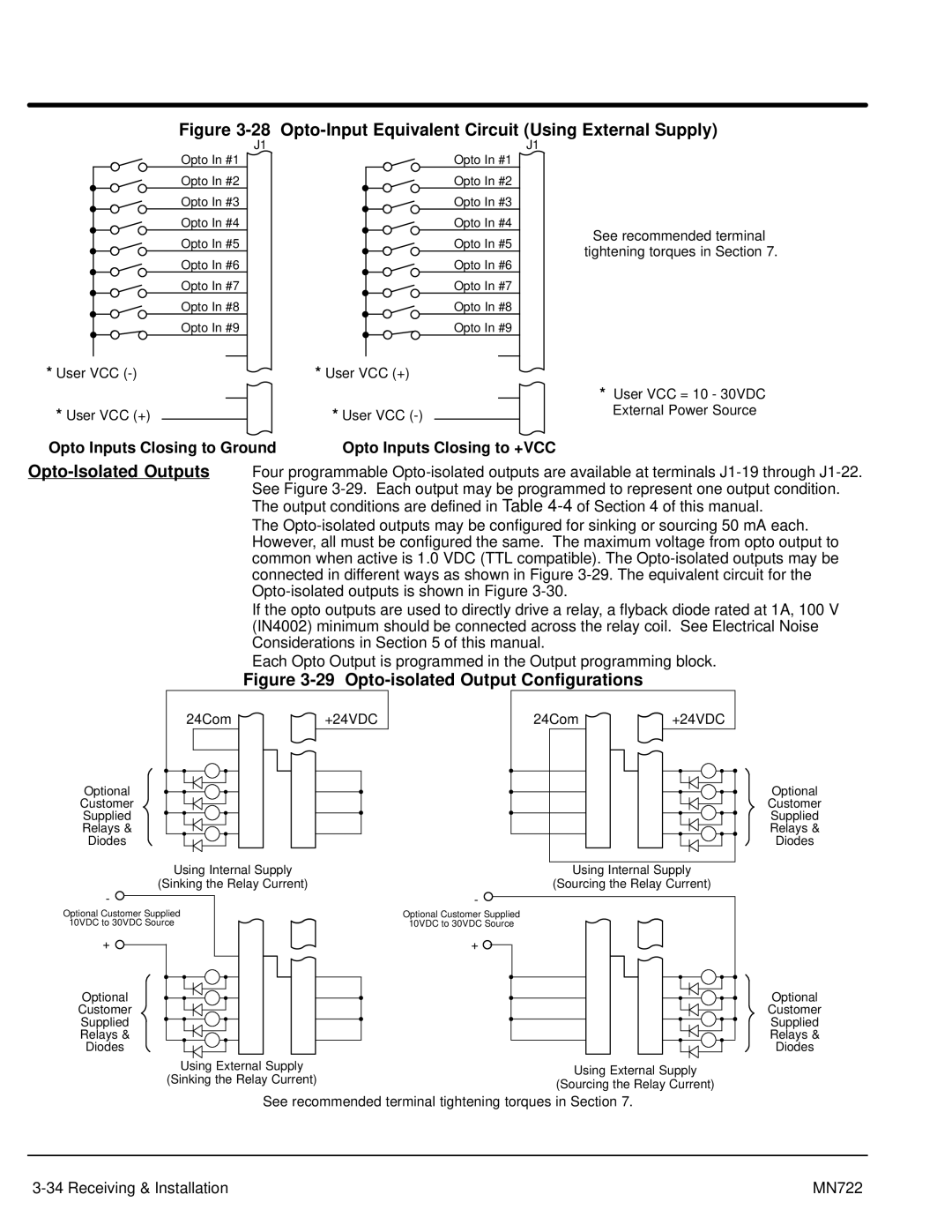
Figure 3-28 Opto-Input Equivalent Circuit (Using External Supply)
Opto In #1
Opto In #2
Opto In #3
Opto In #4
Opto In #5
Opto In #6
Opto In #7
Opto In #8
Opto In #9
*User VCC (-)
*User VCC (+)
J1
8
9
10
11
12
13
14
15
16
17
39
40
Opto In #1
Opto In #2
Opto In #3
Opto In #4
Opto In #5
Opto In #6
Opto In #7
Opto In #8
Opto In #9
*User VCC (+)
*User VCC
J1
8
9
10
11
12
13
14
15
16
17
39
40
See recommended terminal tightening torques in Section 7.
*User VCC = 10 - 30VDC External Power Source
Opto Inputs Closing to Ground | Opto Inputs Closing to +VCC |
The
If the opto outputs are used to directly drive a relay, a flyback diode rated at 1A, 100 V (IN4002) minimum should be connected across the relay coil. See Electrical Noise Considerations in Section 5 of this manual.
Each Opto Output is programmed in the Output programming block.
Figure 3-29 Opto-isolated Output Configurations
24Com | 17 | |
| 18 | |
| 19 | |
Optional | 20 | |
Customer | 21 | |
Supplied | ||
Relays & | 22 | |
Diodes | ||
|
39
![]() 41 42 43 44
41 42 43 44
+24VDC
24Com | 17 | 39 | +24VDC |
| 18 |
|
|
| 19 | 41 |
|
| 20 | 42 | Optional |
| 21 | 43 | Customer |
| Supplied | ||
| 22 | 44 | Relays & |
| Diodes | ||
|
|
|
| Using Internal Supply |
| |
| (Sinking the Relay Current) | ||
- |
|
| |
Optional Customer Supplied |
| ||
10VDC to 30VDC Source |
| ||
+ | 17 | 39 | |
18 |
| ||
|
| ||
| 19 | 41 | |
Optional | 20 | 42 | |
Customer | 21 | 43 | |
Supplied | |||
Relays & | 22 | 44 | |
Diodes | |||
|
| ||
| Using External Supply | ||
| (Sinking the Relay Current) | ||
Using Internal Supply |
(Sourcing the Relay Current) |
- ![]()
Optional Customer Supplied
10VDC to 30VDC Source
17 | 39 |
| |
+ |
|
| |
18 |
|
| |
19 | 41 |
| |
20 | 42 | Optional | |
21 | 43 | Customer | |
Supplied | |||
22 | 44 | Relays & | |
Diodes | |||
|
|
Using External Supply
(Sourcing the Relay Current)
See recommended terminal tightening torques in Section 7.
MN722 |
