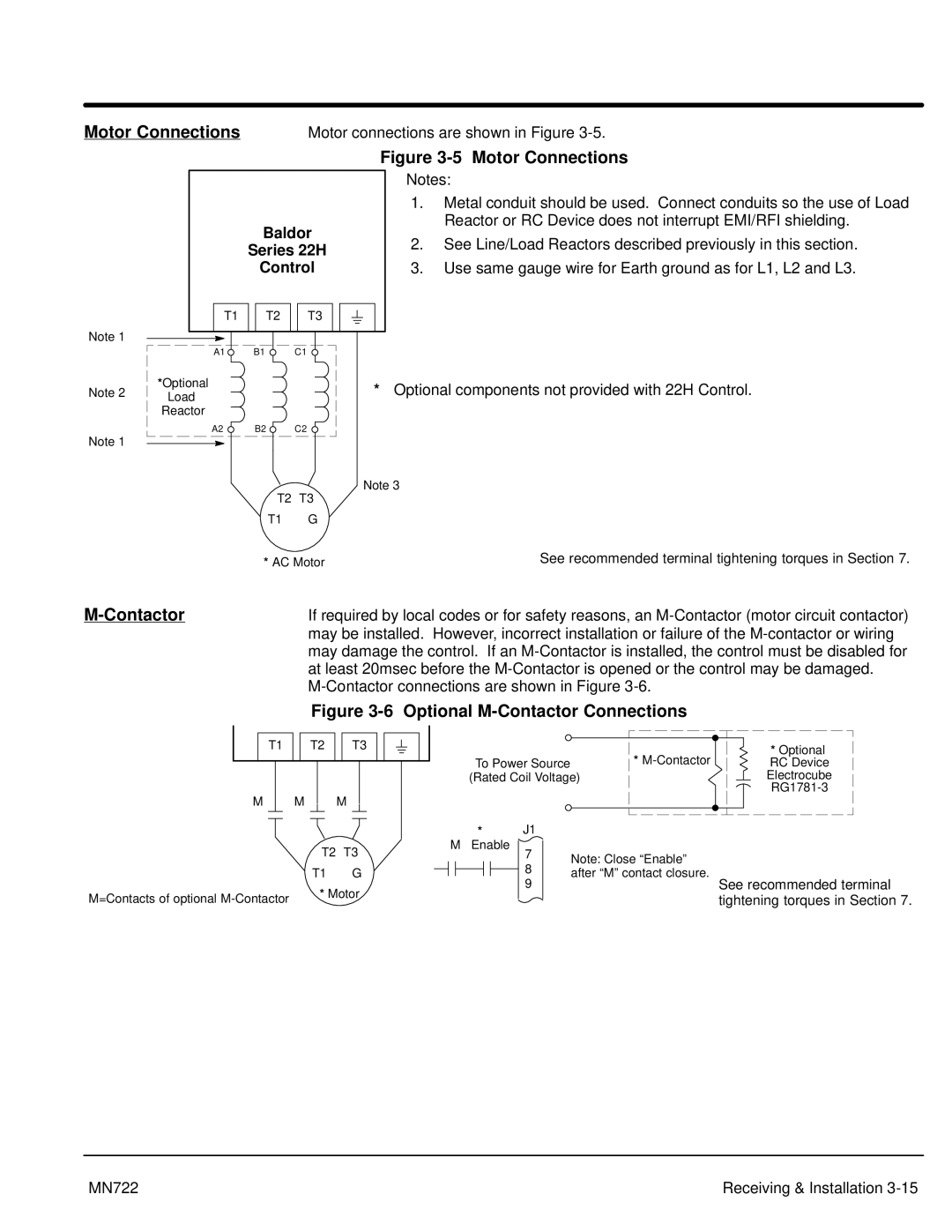
Motor Connections | Motor connections are shown in Figure |
Figure 3-5 Motor Connections
|
| Baldor | |
|
| Series 22H | |
|
| Control | |
| T1 | T2 | T3 |
Note 1 |
|
|
|
| A1 | B1 | C1 |
Note 2 | *Optional |
| * |
Load |
| ||
|
|
| |
| Reactor |
|
|
| A2 | B2 | C2 |
Notes:
1.Metal conduit should be used. Connect conduits so the use of Load Reactor or RC Device does not interrupt EMI/RFI shielding.
2.See Line/Load Reactors described previously in this section.
3.Use same gauge wire for Earth ground as for L1, L2 and L3.
Optional components not provided with 22H Control.
Note 1 |
|
|
|
| Note 3 | ||
|
|
| |||||
|
|
|
|
|
|
| |
|
|
|
| T2 | T3 | ||
|
|
|
| ||||
|
|
|
|
| |||
|
|
| T1 | G |
| ||
|
|
| * AC Motor | See recommended terminal tightening torques in Section 7. | |||
| If required by local codes or for safety reasons, an |
| may be installed. However, incorrect installation or failure of the |
| may damage the control. If an |
| at least 20msec before the |
|
|
| Figure |
|
|
|
|
|
|
|
|
|
|
|
|
|
|
|
|
|
|
|
|
|
| T1 |
| T2 |
| T3 |
|
|
|
|
|
|
| ||||||
|
|
|
|
|
|
|
|
|
|
| |||||||||
|
|
|
|
|
|
|
|
|
|
|
|
|
|
|
|
|
|
|
|
|
|
|
|
|
|
|
|
|
|
|
|
|
|
|
|
|
|
|
|
| M | M | M | ||||||||||||||||
|
|
|
|
|
|
|
|
|
|
|
|
| |||||||
|
|
|
|
|
|
|
|
|
|
|
|
|
|
|
|
|
|
|
|
|
|
|
|
|
|
| T2 |
| T3 | ||||||||||
|
|
|
|
|
|
| T1 |
| G | ||||||||||
M=Contacts of optional |
|
| * Motor | ||||||||||||||||
|
|
|
|
|
|
|
|
|
|
|
|
|
|
| |||||
|
| * |
|
|
|
|
| * Optional |
|
|
|
|
|
|
| ||
To Power Source |
|
|
|
|
| RC Device | ||
(Rated Coil Voltage) |
|
|
|
|
|
| Electrocube | |
|
|
|
|
|
| |||
|
|
|
|
|
|
|
| |
|
|
|
|
|
|
| ||
|
|
|
|
|
|
|
|
|
*J1
M Enable
7Note: Close “Enable”
8 | after “M” contact closure. |
9 | See recommended terminal |
tightening torques in Section 7.
MN722 | Receiving & Installation |