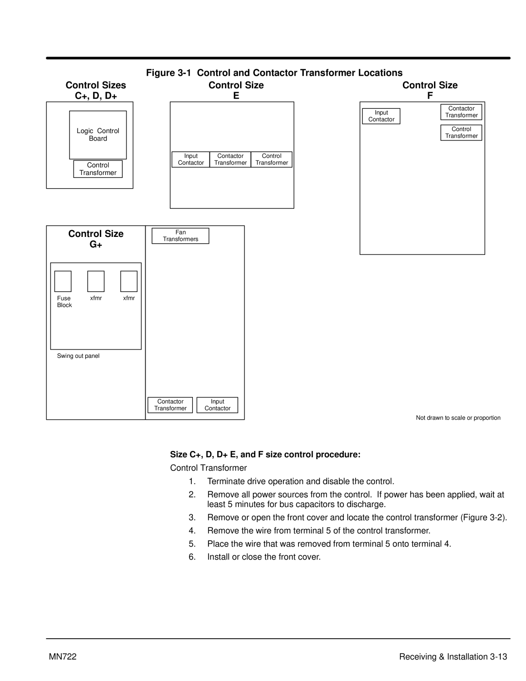
Figure 3-1 Control and Contactor Transformer Locations
Control Sizes
C+, D, D+
Logic Control
Board
Control
Transformer
Control Size
E
Input Contactor Control Contactor Transformer Transformer
Control Size
F
Contactor
InputTransformer
Contactor
Control
Transformer
Control Size
G+
Fan
Transformers
Fuse | xfmr | xfmr |
Block |
|
|
Swing out panel
Contactor
Transformer
Input
Contactor
Not drawn to scale or proportion
Size C+, D, D+ E, and F size control procedure:
Control Transformer
1.Terminate drive operation and disable the control.
2.Remove all power sources from the control. If power has been applied, wait at least 5 minutes for bus capacitors to discharge.
3.Remove or open the front cover and locate the control transformer (Figure
4.Remove the wire from terminal 5 of the control transformer.
5.Place the wire that was removed from terminal 5 onto terminal 4.
6.Install or close the front cover.
MN722 | Receiving & Installation |