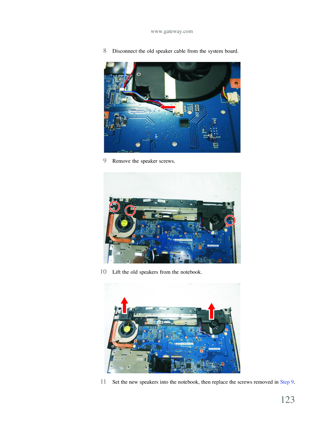
P-79
SERVICEGUIDE
Copyright
Revision History
Updates
Date
Contents
Contents
Page
Contents
Preface Features System block diagram
System specifications
Hardware specifications and configurations Notebook product tour
CHAPTER1
Preface
Features
Conventions
General information
Storage subsystem
Display and graphics
Input devices
Audio
Communication
Dimension and Weight
I/O Ports and devices
Security
System block diagram
BIOS
Hardware specifications and configurations
Controllers
CHAPTER 1 System specifications
Memory
Specification
Specification
Hard Disk Drive
Specification
CHAPTER 1 System specifications
Specification
Optical drive
Specification
Specification
CHAPTER 1 System specifications
Video subsystem
Inverter
Specification
ItemSpecification
Pointing device
Keyboard
Memory card reader
Specification
ExpressCard
Cardbus
Audio
Specification
Bluetooth
Wired LAN
Wireless LAN
Specification
Specification
Buttons/Indicators/Ports
Specification
Specification
Camera
Fingerprint reader
Fans
CHAPTER 1 System specifications
Power supply
Battery
Power savings
Specification
Front View
Notebook product tour
Left View
CHAPTER 1 System specifications
Right View
Rear View
CHAPTER 1 System specifications
Power connector
Bottom View
Keyboard area
CHAPTER 1 System specifications
Icon
LCD panel
CHAPTER 1 System specifications
Using the status indicators
Key types
Using the keyboard
CHAPTER 1 System specifications
System key combinations
Using the fingerprint reader
To run the Gateway Fingerprint Solution program
CHAPTER 1 System specifications
Using the EZ Pad touchpad
Move the pointer on the screen Select an object on the screen
CHAPTER 1 System specifications
Button Description
Using the optional multimedia panel
CHAPTER 1 System specifications
Using the webcam
Icon
Button
Description
2 Click Start camera. The Camera Assistant opens
CHAPTER 1 System specifications
Clearing password check and BIOS recovery
BIOS Setup Utility BIOS flash utility Removing a password lock
CHAPTER2
System utilities
BIOS Setup Utility
Navigating the BIOS Setup Utility
CHAPTER 2 System utilities
Main screen
BIOS Setup Utility screens
Advanced screen
CHAPTER 2 System utilities
The table below describes the parameters found on this screen
Supervisor or
Security screen
CHAPTER 2 System utilities
Setting a Password
To set the User password
CHAPTER 2 System utilities
Press ENTER, then re-enter the current password
5 Press ENTER. The screen displays the following 6 Press ENTER
4 Retype the password in the Confirm New Password field
Exit
Boot
CHAPTER 2 System utilities
Specific
The table below describes the options on this screen
CHAPTER 2 System utilities
BIOS flash utility
Removing a HDD password lock
Removing a password lock
Clearing Password Check
Clearing password check and BIOS recovery
G116
CHAPTER 2 System utilities
BIOS Recovery by Crisis Disk
Steps for BIOS Recovery by Crisis Disk
Steps for Creating the Crisis Disk in Windows XP/Vista
CHAPTER 2 System utilities
4 Keep the default settings and then click on the Start button
7 Press No if you do not want to create another Crisis Disk
6 The Crisis Disk will be created after a few seconds
CHAPTER 2 System utilities
Replacing the LCD assembly Replacing the LCD panel
Replacing the IEEE 802.11 wireless card Replacing the CMOS battery
Replacing the LCD assembly lid Replacing the palm rest
Replacing the fingerprint reader Replacing the Bluetooth module
Preventing static electricity discharge
Tape
CHAPTER 3 Replacing notebook components
Preparing your work space
CHAPTER 3 Replacing notebook components
Tools required
To disassemble the notebook, you need the following tools
Flat screwdriver Phillips screwdriver Scribe or non-marring tool
Preparing the notebook
Removing the battery
Adding or replacing memory modules
CHAPTER 3 Replacing notebook components
1 Complete the steps in “Preparing the notebook” on page
5 Pull the memory module out of the slot
7 Press the card down until it clicks into place
8 Replace the memory bay cover, then tighten the cover screws
Cooling assembly bay
Replacing the main cooling assembly
CHAPTER 3 Replacing notebook components
1 Complete the steps in “Preparing the notebook” on page
Page
CHAPTER 3 Replacing notebook components
9 Insert the new main cooling assembly into the notebook
Replacing the processor
1 Complete the steps in “Preparing the notebook” on page
Flat-blade driver
Thermal Pad Thermal Grease
CHAPTER 3 Replacing notebook components
1 Complete the steps in “Preparing the notebook” on page
Replacing the IEEE 802.11 wireless card
CHAPTER 3 Replacing notebook components
5 Remove the wireless card screws
6 Pull the card out of the slot
10 Reattach the antenna cables to the connectors
7 Move the antenna cables out of the way
9 Replace the screws removed in Step
The battery is held in place by double-sided tape
Replacing the CMOS battery
Use double-sided tape to hold the new battery in place
CHAPTER 3 Replacing notebook components
1 Complete the steps in “Preparing the notebook” on page
Replacing the hard drive
CHAPTER 3 Replacing notebook components
4 Using the plastic tab, slide the hard drive you are replacing, then remove it
9 Replace the screws that secure the bracket to the drive
7 Remove the bracket from the old drive
CHAPTER 3 Replacing notebook components
10 Slide the new hard drive kit into your notebook
11 Replace the cover, then tighten the screws
1 Complete the steps in “Preparing the notebook” on page
Replacing the optical drive
Flat-blade driver
Phillips #0 screwdriver
CHAPTER 3 Replacing notebook components
4 Carefully slide the drive out of the drive bay Tip
6 Replace the screw removed in Step
1 Complete the steps in “Preparing the notebook” on page
Replacing the keyboard cover
6 Insert the small flat-blade screwdriver under each of the hinge covers and gently pry them up
CHAPTER 3 Replacing notebook components
10 Remove the old keyboard cover
Long screws
Replacing the keyboard
CHAPTER 3 Replacing notebook components
1 Complete the steps in “Preparing the notebook” on page
The keyboard cable is correctly oriented if it is not twisted
10 Replace the screws removed in Step
CHAPTER 3 Replacing notebook components
1 Complete the steps in “Preparing the notebook” on page
Replacing the inverter
6 Carefully separate the front and back of the LCD panel assembly
5 Remove the screws from the front of the LCD panel assembly
7 Remove the screws connecting the inverter to the LCD panel lid
CHAPTER 3 Replacing notebook components
12 Replace the LCD panel assembly screws removed in Step
Replacing the webcam
CHAPTER 3 Replacing notebook components
1 Complete the steps in “Preparing the notebook” on page
5 Remove the screws from the front of the LCD panel assembly
6 Carefully separate the front and back of the LCD panel assembly
7 Disconnect the webcam cable from the webcam
CHAPTER 3 Replacing notebook components
9 Remove the old webcam 10 Install the new webcam
1 Complete the steps in “Preparing the notebook” on page
Replacing the lid latches
5 Remove the screws from the front of the LCD panel assembly
6 Carefully separate the front and back of the LCD panel assembly
CHAPTER 3 Replacing notebook components
8 Remove the old lid latches 9 Install the new lid latches
Replacing the LCD assembly
CHAPTER 3 Replacing notebook components
1 Complete the steps in “Preparing the notebook” on page
The LCD video cable connector is fragile
CHAPTER 3 Replacing notebook components
11 Lift the LCD panel assembly up and away from the notebook
Page
Replacing the LCD panel
CHAPTER 3 Replacing notebook components
1 Complete the steps in “Preparing the notebook” on page
6 Remove the rubber inserts from the front of the LCD panel assembly
7 Remove the screws from the front of the LCD panel assembly
8 Carefully separate the front and back of the LCD panel assembly
CHAPTER 3 Replacing notebook components
9 Remove the screws that secure the LCD panel to the LCD panel lid
Magnet bracket and magnet
20 Replace the LCD panel assembly screws removed in Step
21 Replace the rubber inserts removed in Step
25 Turn the notebook over so the bottom is facing up
Replacing the LCD panel hinges and bracket
CHAPTER 3 Replacing notebook components
1 Complete the steps in “Preparing the notebook” on page
6 Remove the rubber inserts from the front of the LCD panel assembly
7 Remove the screws from the front of the LCD panel assembly
8 Carefully separate the front and back of the LCD panel assembly
CHAPTER 3 Replacing notebook components
Magnet bracket and magnet
22 Make sure that the magnet has remained in the magnet bracket
Replacing the LCD assembly lid
CHAPTER 3 Replacing notebook components
1 Complete the steps in “Preparing the notebook” on page
19 Turn the notebook over so the bottom is facing up
Replacing the palm rest
CHAPTER 3 Replacing notebook components
1 Complete the steps in “Preparing the notebook” on page
8 Turn the notebook over so the bottom is facing up
9 Remove the screws from the bottom of the notebook
10 Turn the notebook over so the top is facing up
Small screws
CHAPTER 3 Replacing notebook components
22 Replace the LCD assembly by following the steps in “Replacing the LCD assembly” on page
Replacing the touchpad board
CHAPTER 3 Replacing notebook components
1 Complete the steps in “Preparing the notebook” on page
10 Remove any tape on top of the cable
9 Remove the screws from the touchpad board bracket
The touchpad cable is correctly oriented if the blue side is showing
CHAPTER 3 Replacing notebook components
22 If the notebook has wireless networking built in, reconnect the wireless antennas by following the steps in “Replacing the IEEE 802.11 wireless card” on page
Replacing the touchpad button board
CHAPTER 3 Replacing notebook components
1 Complete the steps in “Preparing the notebook” on page
Page
CHAPTER 3 Replacing notebook components
1 Complete the steps in “Preparing the notebook” on page
Replacing the fingerprint reader
9 Release from the latches and remove the fingerprint reader from the palm rest
1 Complete the steps in “Preparing the notebook” on page
Replacing the Bluetooth module
CHAPTER 3 Replacing notebook components
1 Complete the steps in “Preparing the notebook” on page
Replacing the modem
CHAPTER 3 Replacing notebook components
8 Remove the screws securing the modem to the system board
10 Lift the modem off of the system board
11 Install the new modem on the system board
Replacing the speakers
CHAPTER 3 Replacing notebook components
1 Complete the steps in “Preparing the notebook” on page
8 Disconnect the old speaker cable from the system board
9 Remove the speaker screws
10 Lift the old speakers from the notebook
CHAPTER 3 Replacing notebook components
1 Complete the steps in “Preparing the notebook” on page
Replacing the system board and VGA cooling assembly
CHAPTER 3 Replacing notebook components
12 Unplug the Bluetooth module from the system board one connector
15 Remove the modem cable from the system board retaining clips
17 Unplug the fans from the system board
CHAPTER 3 Replacing notebook components
18 Remove the EMI shield screws. Then remove the EMI shield
19 Remove the system board screws
20 Carefully remove the system board
21 Disconnect the VGA cooling assembly cable from the system board
CHAPTER 3 Replacing notebook components
25 Replace the VGA cooling assembly on the new system board
33 Replace the LCD assembly by following the steps in “Replacing the LCD assembly” on page
Replacing the modem jack/USB board
CHAPTER 3 Replacing notebook components
1 Complete the steps in “Preparing the notebook” on page
12 Remove the modem jack/USB board screw
CHAPTER 3 Replacing notebook components
1 Complete the steps in “Preparing the notebook” on page
Replacing the fans
11 Remove the fan screws 12 Lift the old fan from the system
16 Replace the LCD assembly by following the steps in “Replacing the LCD assembly” on page
CHAPTER 3 Replacing notebook components
Diagnosing problems System test procedures
Troubleshooting
Power-On Self-Test POST error message Index of error messages
Phoenix BIOS beep codes Symptom-to-FRU error messages
System test procedures
Diagnosing problems
Testing the optical drive
Symptoms Verified
Testing the memory
Testing the keyboard or auxiliary input device
Testing the power system
Do not replace a non-defective FRU
Check the battery pack
Check the power adapter
CHAPTER 4 Troubleshooting
“Check the power adapter” on page “Check the battery pack” on page
Power-On Self-Test POST error message
Testing the touchpad
If the symptom is not listed, see “Undetermined problems” on page
Error codes
Index of error messages
Error messages
CHAPTER 4 Troubleshooting
FRU/Action Sequence
Error Messages
No-beep error messages
CHAPTER 4 Troubleshooting
the power system” on page
Code
Phoenix BIOS beep codes
Beeps
POST Routine Description
1-3-4-3
CHAPTER 4 Troubleshooting
Configure advanced cache registers
Install CD ROM for boot
CHAPTER 4 Troubleshooting
Beeps
Code
POST Routine Description
Code
Symptom-to-FRU error messages
Power
CHAPTER 4 Troubleshooting
Sound
Power management
ExpressCard
Memory
Devices
CHAPTER 4 Troubleshooting
Press Fn+F4 repeatedly to switch between LCD, external display, and
Intermittent problems
Undetermined problems
Keyboard and touchpad
Non-Acer devices Printer, mouse, and other external devices
CHAPTER 4 Troubleshooting
Connector locations
System board top connectors System board bottom connectors
CHAPTER5
CHAPTER 5 Connector locations
System board top connectors
System board bottom connectors
CHAPTER 5 Connector locations
Introduction Exploded diagram FRU list
CHAPTER6
FRU Field-Replaceable Unit list
CHAPTER 6 FRU Field-Replaceable Unit list
Introduction
Notebook chassis
Exploded diagram
CHAPTER 6 FRU Field-Replaceable Unit list
FRU list
Category
CHAPTER 6 FRU Field-Replaceable Unit list
Category
OEM Part No
CHAPTER 6 FRU Field-Replaceable Unit list
Category
CHAPTER 6 FRU Field-Replaceable Unit list
Category
HDD 250GB 5400RPM SATA WD WD2500BEVT-22ZCT0
CHAPTER 6 FRU Field-Replaceable Unit list
HDD 320GB 5400RPM SATA WD WD3200BEVT-22ZCT0
HDD 500GB 5400RPM WD SATA WD5000BEVT-22ZAT0
Category
CHAPTER 6 FRU Field-Replaceable Unit list
Category
CHAPTER 6 FRU Field-Replaceable Unit list
Category
CHAPTER 6 FRU Field-Replaceable Unit list
APPENDIXA
Model definition and configuration
APPENDIX A Model definition and configuration
APPENDIXB
Test compatible components
Introduction Microsoft Windows Vista Environment Test
Microsoft Windows Vista Environment Test
Introduction
APPENDIX B Test compatible components
Headphone/Microphone Port Test
APPENDIX B Test compatible components
Bluetooth Cell Phone/Headset
Online support information
APPENDIXC
APPENDIX C Online support information
Index
Page
Page
Index
Page
MAN P-79 SVC GDE R1 06/09