www.gateway.com
Replacing the system board and VGA cooling assembly
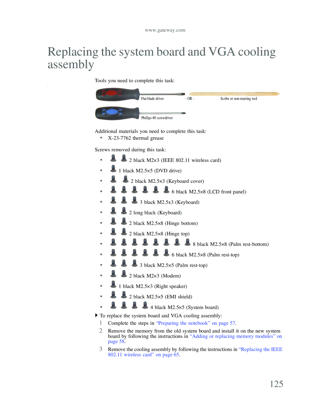
Tools you need to complete this task:
v
- OR - | Scribe or |
Phillips #0 screwdriver
Additional materials you need to complete this task:
•
Screws removed during this task:
•![]()
![]() 2 black M2×3 (IEEE 802.11 wireless card)
2 black M2×3 (IEEE 802.11 wireless card)
•![]() 1 black M2.5×5 (DVD drive)
1 black M2.5×5 (DVD drive)
•
•
•![]()
![]()
![]() 3 black M2.5x3 (Keyboard)
3 black M2.5x3 (Keyboard)
•![]()
![]() 2 long black (Keyboard)
2 long black (Keyboard)
•![]()
![]() 2 black M2.5×8 (Hinge bottom)
2 black M2.5×8 (Hinge bottom)
•![]()
![]() 2 black M2.5×8 (Hinge top)
2 black M2.5×8 (Hinge top)
•
•
•![]()
![]()
![]() 3 black M2.5×5 (Palm
3 black M2.5×5 (Palm
•![]()
![]() 2 black M2×3 (Modem)
2 black M2×3 (Modem)
•![]() 1 black M2.5×3 (Right speaker)
1 black M2.5×3 (Right speaker)
•![]()
![]() 2 black M2.5×5 (EMI shield)
2 black M2.5×5 (EMI shield)
• ![]()
![]()
![]()
![]() 4 black M2.5×5 (System board)
4 black M2.5×5 (System board)
![]() To replace the system board and VGA cooling assembly:
To replace the system board and VGA cooling assembly:
1Complete the steps in “Preparing the notebook” on page 57.
2Remove the memory from the old system board and install it on the new system board by following the instructions in “Adding or replacing memory modules” on page 58.
3Remove the cooling assembly by following the instructions in “Replacing the IEEE 802.11 wireless card” on page 65.