VISTA-40
Recommendations for Proper Protection
Table of Contents
WAY Voice Keypads & Audio Alarm Verification AAV
Relay Outputs & Powerline Carrier Devices
DIP Switch Tables
Setting the REAL-TIME Clock
Testing the System
Summary of System Commands
Part
General Information
Prohibit Program Mode Entry
Access Control
#70 End User Relay Commands
Installer Code
Partitions
Simple, Secure, Reliable
10 Ð
Installing the Control
Knockouts after the circuit board has been installed
Installing the Lock
Pabx
VIM
Standard Phone Line Connections
AUX. Standby Current Draw
Powering the System
Battery Standby Table
AC Power and Battery Connections
Total
Connections diagram. Do not plug in at this time
RPM Device Current # Units Total Current
Device Current # Units Total Current
Keypad Connections
Installing Remote Keypads
14 Ð
Powering Additional Keypads
16 Ð
6139AV Audio Connection
17 Ð
Zone Configurations
Programmable Response Time For Zone
At the last device
Compatible Device Model # Smoke Detectors
Hard-wired Zones 2Ð8
18 Ð
19 Ð
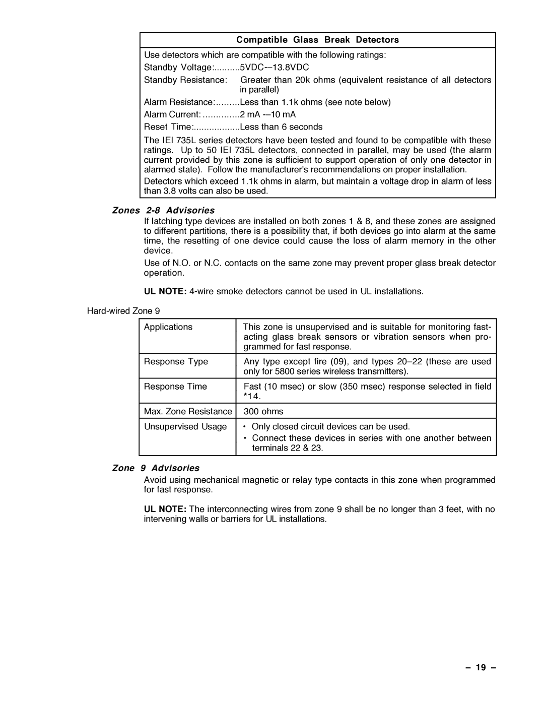
Compatible Glass Break Detectors
20 Ð
Maximum Polling Loop Wire Runs Wire Gauge Max. Length
4275 Dual Element Polling Loop PIR
4208 Eight Zone Polling Loop Expansion Module
4190WH Two Zone Remote Point Module
4278 Quad Element Polling Loop PIR
22 Ð
Wireless Expansion Zones 1Ð63
Feature Series
Following table highlights the features of each receiver
23 Ð
24 Ð
Wrapped around the transmitter
Series Transmitter Zone Types
5801, 5802, etc
25 Ð
5706 Wireless Photoelectric Smoke Detector System Sensor
1 1 W M Door/Window Transmitter w/Reed Switch
5727 Wireless Keypad
5775 Wireless PIR
27 Ð
J7 Connector for Voltage Triggers
Partition
System. Note that keyswitch arming may only be used in one
Not intended for use in UL Listed applications
Ground Start Module Connections
LED indications are defined as follows Green Meaning
Remote Keyswitch Wiring
29 Ð
Remote Keypad Sounding Connections
Using a Trigger to Activate a NON-ADEMCO AAV Unit
30 Ð
Transformer Connections
Section
31 Ð
32 Ð
Assigned to partition 1 using #93 Menu Mode, Device
Goto command
4285 Phone Module
33 Ð
Color Lead Terminal On Control
Ê4285 Terminal Connects to
Advisory
34 Ð
Phone Module Wiring Connections
Second Pauseê this is 555Ð1212. I Cant Come to the Phone
Just NOW. Please Leave a Message After the Tone
35 Ð
WAY Voice Keypads
Information For
6139AV Audio
VIM Module
Programming
6139AV Keypad Audio
Level Adjustment
6139AV Keypad
Protection zone
38 Ð
Important Notes
39 Ð
External Sounders
40 Ð
Programming Procedures
41 Ð
General Information
Program system-wide global data fields
Use #93 Menu Mode for device programming
Use #93 Menu Mode for zone programming
Exit Programming Mode
Zone Types
IMPORTANT! Fault Annunciation
Data Field Programming
Summary of Data Field Programming Commands
Programming SYSTEM-WIDE Global Data Fields
Field Group
Index to Programming Fields
46 Ð
Data Field Descriptions
Normally Closed
Power Up
Output Enable
Previous State
Download
Download Command Enables 2nd page Field Download Callback
Access Code
For Keyswitch Dial Tone Pause
Dialer Options
2ND page Fields
Second page Fields
RF Button
Global Arm
Force Bypass
Programming PARTITION-SPECIFIC Fields
Programming PARTITION-SPECIFIC Data Fields
Exit Delay
Enable Dialer
Burg. Alarm
Comm. Delay
Receivers should be programmed via Device programming
Number of Partitions 1*32 receiver type. In addition
55 Ñ
Zone PROG? 1=YES 0=NO Enter ZN no =QUIT
Zone Type Zone Disabled Partition Report Code
56 Ð
Prog AS RF1
Input Type RF TRANS. RF Loop Number
57 Ð
ZT P RC INL
Serial # PROG? 0=NO 1=YES Enter Zone no =QUIT
58 Ð
59 Ð
Number whenever the alpha keypad displays a custom word
Entering Zone
Substitute custom words, if desired. If not programmed for
Substitutes, the phone module will only annunciate the zone
Ready to ARM
Creating Partition Descriptors
61 Ð
62 Ð
Character Ascii Chart For Adding Custom Words
63 Ð
Device PROG?
64 Ð
VIM PARTITION? MAX 2WAY T.O
Chime Others VIM TEXT? VIM AC Loss Auto Call Back
Start
Action a
65 Ð
66 Ð
O P
Menus
Enter Relay no =QUIT
67 Ð
68 Ð
Ex. Relay #2 programming
Enter Desc
Start Event Trouble Start ZN Type
RLY Voice DESCR? 0=NO 1=YES
Enter Relay no
70 Ð
Word Index
Custom Index #?
Custom Word no =QUIT Enter Index #
Eeee
System Communication
Communication Formats
Cccc
72 Ð
Table of Contact ID Event Codes
EEE
73 Ð
Communication Programming
Table of Default Programming Commands
74 Ð
Ademco
76 Ð
77 Ð
Communication Defaults for LOW Speed Format *94 then *80
78 Ð
Second Digit
80 Ð
ARM Stay & Time SET Report Codes
82 Ð
83 Ð
84 Ð
What Is Downloading? How Does Downloading Work?
Downloading
Remote Downloading
Control/Comm Access
File Access
85 Ð
Direct Wire Downloading Connections
Direct Wire Downloading
86 Ð
Procedure
Setting the REAL-TIME Clock
87 Ð
88 Ð
System Operation & Testing
System Operation
Security Access Codes
Level Title Functions Permitted
Manager Level
Operator
Levels
91 Ð
Goto Function
92 Ð
93 Ð
Keypad Functions
Alpha Keypads Only
M o d e Features For Each Arming Mode
Summary of Arming Modes
Keypads Only
Other Trouble Conditions 96 Ð
Check Messages
97 Ð
VIM Voice Interface Module Operator Functions
Enter 0 = Recent
Operator Commands
Event Logging
Key Function Comments
99 Ð
Turning Off Test mode
Testing the System
100 Ð
101 Ð
Way Voice Test Mode
102 Ð
To the Installer
Arming, Disarming
Summary of System Commands
Types of Commands Desired Function Procedure
Silencing Commands
104 Ð
105 Ð
Regulatory Agency Statements
106 Ð
Canadian Department of Communications DOC Statement
107 Ð
Zone Expander
4192D/4192SDT/4192CP Smoke Detectors
4190WH Zone Expander
108 Ð
4275 PIR 4278 PIR
Reed Contact
Surface Mount
109 Ð
Digital Communicator
Specifications
111 Ð
¥ Read the Instructions
112 Ð
Limitations of this Alarm System
VISTA-40 Summary of Connections
AL ARM Device Manufacturing CO
Ademco Limited Warranty
Program TOOL? 0 = NO, 1 = YES Input S/N L
Enrolling Through Zone Programming #93
NTE R ZN no
Proceeding to the next zone
That you confirm the programming of every device before
Program TOOL? 0 = NO, 1 = YES
Enrolling Through Sequential Mode #93
No serial number programmed
Devices enabled programmed
An input type of RF, UR, BR, or SL if serial polling loop
Loop number programmed
Confirmed SL1
Clear RF SERIAL#?
RF Serial Number Clear Mode #93
Alarm Device Manufacturing CO