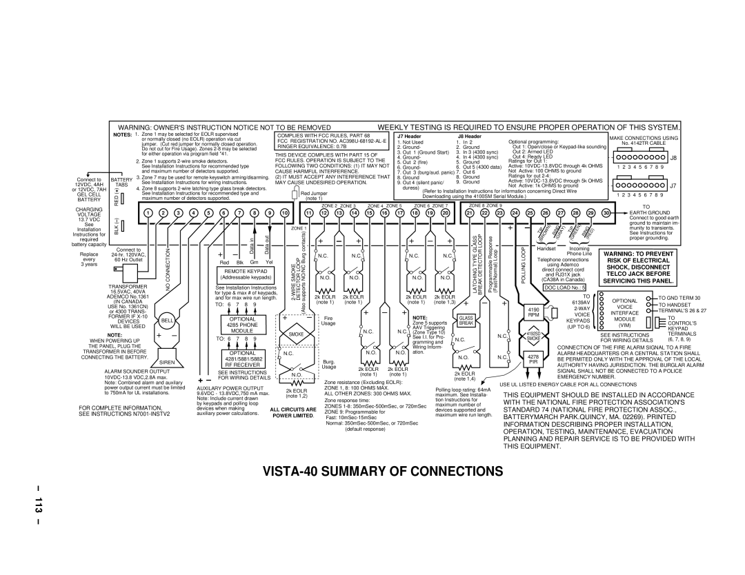
| WARNING: OWNER'S INSTRUCTION NOTICE NOT TO BE REMOVED |
|
| WEEKLY TESTING IS REQUIRED TO ENSURE PROPER OPERATION OF THIS SYSTEM. | |||||||||||||||||||||||||||||||||||
| NOTES: 1. Zone 1 may be selected for EOLR supervised |
|
|
| COMPLIES WITH FCC RULES, PART 68 |
| J7 Header |
|
|
| J8 Header |
|
|
|
|
|
|
|
|
|
|
| MAKE CONNECTIONS USING | ||||||||||||||||
|
| or normally closed (no EOLR) operation via cut |
|
|
| FCC REGISTRATION NO. | 1. Not Used |
|
|
| 1. In 2 |
|
| Optional programming: |
|
|
| ||||||||||||||||||||||
|
| jumper. (Cut red jumper for normally closed operation. |
|
|
|
|
|
|
|
|
| No. 4142TR CABLE | |||||||||||||||||||||||||||
|
|
| RINGER EQUIVALENCE: 0.7B |
|
|
|
|
|
|
|
|
|
| ||||||||||||||||||||||||||
|
| Do not cut for Fire Usage). Zones |
|
|
| 2. Ground- |
|
|
| 2. | Ground |
|
| Out 1: Open/close or |
|
| |||||||||||||||||||||||
|
|
|
|
|
|
|
|
|
|
| 3. Out | 1 (Ground Start) |
| 3. | In 3 (4300 sync) | Out 2: Armed LED |
|
|
|
|
|
| |||||||||||||||||
|
| for either operation via program field *41. |
|
|
|
| THIS DEVICE COMPLIES WITH PART 15 OF |
|
|
|
|
|
|
|
| ||||||||||||||||||||||||
|
|
|
|
|
|
| 4. Ground- |
|
|
| 4. In 4 (4300 sync) | Out 4: Ready LED |
|
|
|
|
| J8 | |||||||||||||||||||||
|
|
|
|
|
|
|
|
|
|
|
| FCC RULES. OPERATION IS SUBJECT TO THE |
|
|
|
|
|
|
|
| |||||||||||||||||||
|
| 2. Zone 1 supports |
|
|
|
| 5. Out | 2 (fire) |
|
| 5. | Ground |
|
| Ratings for Out 1: |
|
|
|
|
|
| ||||||||||||||||||
|
| See Installation Instructions for recommended type |
|
| FOLLOWING TWO CONDITIONS: (1) IT MAY NOT | 6. Ground- |
|
|
| 6. Out 5 (4300 data) | Active: | 1 2 3 4 5 6 7 8 9 | |||||||||||||||||||||||||||
|
| and maximum number of detectors supported. |
|
|
| CAUSE HARMFUL INTERFERENCE. |
|
| 7. Out | 3 (burg/aud. panic) | 7. | Out 6 |
|
| Not | Active: 100 OHMS to ground |
|
|
|
| |||||||||||||||||||
Connect to | BATTERY | 3. Zone 7 may be used for remote keyswitch arming/disarming. | (2) IT MUST ACCEPT ANY INTERFERENCE THAT | 8. Ground |
|
|
| 8. Ground |
|
| Ratings for out |
|
|
|
|
|
| ||||||||||||||||||||||
|
|
|
|
| Active: |
|
| ||||||||||||||||||||||||||||||||
12VDC, 4AH | TABS | See Installation Instructions for wiring instructions. |
|
| MAY CAUSE UNDESIRED OPERATION. |
| 9. Out 4 (silent panic/ |
| 9. | Ground |
|
| Not Active: 1k OHMS to ground |
|
|
| J7 | ||||||||||||||||||||||
4. Zone 8 supports |
|
|
|
|
|
|
|
| duress) |
|
|
|
|
|
|
|
|
|
| ||||||||||||||||||||
or 12VDC, 7AH | ) |
|
|
|
|
|
|
|
|
|
|
|
|
|
|
|
|
|
| ||||||||||||||||||||
+ | See Installation Instructions for recommended type and |
|
| Red Jumper |
|
|
|
|
| (Refer to Installation Instructions for information concerning Direct Wire |
|
|
|
| |||||||||||||||||||||||||
GEL CELL | ( |
|
|
|
|
|
|
|
|
| 1 2 3 4 5 6 7 8 9 | ||||||||||||||||||||||||||||
RED |
|
|
|
|
|
|
| Downloading using the 4100SM Serial Module.) |
|
|
|
|
|
|
| ||||||||||||||||||||||||
BATTERY | maximum number of detectors supported. |
|
|
|
|
| (note 1) |
|
|
|
|
|
|
|
|
|
|
|
|
|
|
|
|
|
|
|
|
|
|
|
| ||||||||
|
|
|
|
|
|
|
|
|
|
|
|
|
|
|
|
|
|
|
|
|
|
|
|
|
|
|
|
|
| ||||||||||
CHARGING |
|
|
|
|
|
|
|
|
|
|
|
|
|
| ZONE 2 ZONE 3 | ZONE 4 ZONE 5 | ZONE 6 ZONE 7 |
|
| ZONE 8 ZONE 9 |
|
|
|
|
|
|
|
|
| TO |
| ||||||||
| 1 | 2 | 3 | 4 | 5 | 6 | 7 |
| 8 | 9 | 10 | 11 |
| 12 | 13 | 14 | 15 | 16 | 17 | 18 | 19 | 20 |
|
| 21 | 22 | 23 | 24 |
| 25 |
| 26 | 27 | 28 | 29 | 30 | EARTH GROUND | ||
VOLTAGE |
|
|
|
|
|
|
| ||||||||||||||||||||||||||||||||
|
|
|
|
|
|
|
|
|
|
|
|
|
|
|
|
|
|
|
|
|
|
|
|
|
|
|
|
|
|
|
|
|
|
|
|
| Connect to good earth | ||
13.7 VDC | ) |
|
|
|
|
|
|
|
|
|
|
|
|
|
|
|
|
|
|
|
|
|
|
|
|
|
|
|
|
|
|
|
|
|
|
|
| ||
– |
|
|
|
|
|
|
|
|
|
|
|
|
|
|
|
|
|
|
|
|
|
|
|
|
|
|
|
|
|
|
|
|
|
|
|
| ground to maintain im- | ||
See | ( |
|
|
|
|
|
|
|
|
|
|
|
|
|
|
|
|
|
|
|
|
|
|
|
|
|
|
| + | – |
| (BROWN) | (GRAY) | (GREEN) |
|
| |||
required | BLK |
|
|
|
|
|
|
| in |
| out |
|
|
| + | – | + |
|
| + | – | + |
|
|
|
|
|
| (RED) |
|
|
| |||||||
Installation |
|
|
|
|
|
|
|
|
|
|
| ZONE 1 |
|
|
|
|
|
|
|
|
|
|
|
|
|
|
| TIP | RING | TIP | RING |
| munity to transients. | ||||||
Instructions for |
| CONNECTIONNO |
|
|
| and for max wire run length. | 2k EOLR |
| 2k EOLR |
| 2k EOLR |
| 2k EOLR |
| LATCHINGTYPE GLASS DETECTORBREAK LOOP | ProgrammableResponse | (Fast/Normal)Loop |
| POLLINGLOOP |
|
| See Instructions for | |||||||||||||||||
| ADEMCO No.1361 |
|
|
|
|
|
|
|
|
|
|
|
|
| TO |
|
| TO GND TERM 30 | |||||||||||||||||||||
|
|
|
|
|
|
|
|
|
|
|
|
|
|
|
|
|
|
|
|
|
|
|
|
|
|
|
|
|
|
|
|
|
|
|
|
|
| proper grounding. | |
battery capacity | Connect to |
|
|
|
|
|
| Data |
| Data |
|
|
|
|
|
|
|
|
|
|
|
|
|
|
|
|
|
|
| Handset | Incoming |
|
|
| |||||
Replace |
|
|
|
| + | – |
|
|
|
|
|
| N.C. |
| N.C. |
|
| N.C. |
| N.C. |
|
|
|
|
|
|
|
|
|
|
| Phone Line | WARNING: TO PREVENT | ||||||
every | 60 Hz Outlet |
|
|
|
| Red | Blk | Grn | Yel |
|
|
|
|
|
|
|
|
|
|
|
|
|
|
|
|
|
| Telephone connections | RISK OF ELECTRICAL | ||||||||||
3 years |
|
|
|
|
|
|
|
|
|
|
|
|
|
|
|
|
|
|
|
|
|
|
|
|
|
|
|
|
|
|
|
| using Ademco |
| SHOCK, DISCONNECT | ||||
|
|
|
|
|
|
| REMOTE KEYPAD |
|
|
|
|
|
|
|
|
|
|
|
|
|
|
|
|
|
|
|
|
| direct connect cord | ||||||||||
|
|
|
|
|
|
|
|
|
|
|
|
|
|
|
|
|
|
|
|
|
|
|
|
|
|
|
| and RJ31X jack |
| TELCO JACK BEFORE | |||||||||
|
|
|
|
|
|
| (Addressable keypads) |
|
|
| N.O. |
| N.O. |
|
|
| N.O. |
| N.O. |
|
|
|
|
|
|
|
|
|
| ||||||||||
|
|
|
|
|
|
|
|
|
|
|
|
|
|
|
|
|
|
|
|
|
|
|
| (CA38A in Canada) | SERVICING THIS PANEL. | ||||||||||||||
| TRANSFORMER |
|
|
|
|
|
|
|
|
|
|
|
|
|
|
|
|
|
|
|
|
|
|
|
|
|
|
|
|
|
| ||||||||
|
|
|
|
| See Installation Instructions |
|
|
|
|
|
|
|
|
|
|
|
|
|
|
|
|
|
|
|
| DOC LOAD No.: 5 |
|
|
| ||||||||||
| 16.5VAC, 40VA |
|
|
|
| for type & max # of keypads, |
|
|
|
|
|
|
|
|
|
|
|
|
|
|
|
|
|
|
|
|
|
|
|
|
|
|
| ||||||
| (IN CANADA |
|
|
|
| TO: 6 | 7 | 8 | 9 |
|
| (Also | (note 1) |
| (note 1) |
|
| (note 1) |
| (note 1,3) |
| + | – | + |
|
|
|
|
|
| 6139AV |
| OPTIONAL | TO HANDSET | |||||
| or 4300 TRANS- |
|
|
|
|
|
|
|
|
|
|
|
|
| 4190 |
|
|
|
| VOICE | |||||||||||||||||||
|
|
|
|
|
|
|
|
|
|
|
|
|
|
|
|
|
|
|
|
|
|
|
|
|
|
|
|
|
|
|
|
|
| TERMINAL'S 26 & 27 | |||||
| USE No. 1361CN) |
|
|
|
|
|
|
|
|
|
|
|
|
|
|
| + | – | + |
|
|
|
|
|
|
|
|
|
|
|
|
|
|
|
| ||||
|
|
|
|
|
|
|
|
|
|
|
|
|
|
|
|
|
|
|
|
|
|
|
|
|
|
|
|
|
|
|
|
| INTERFACE |
| |||||
| FORMER IF |
|
|
|
|
|
|
|
|
| + | – |
| Fire |
|
| NOTE: |
|
| GLASS |
|
|
|
| RPM |
|
|
| VOICE |
| TO | ||||||||
| BELL |
|
| OPTIONAL |
|
|
|
|
|
|
|
|
|
|
|
|
|
|
|
|
| KEYPADS |
| MODULE | |||||||||||||||
| DEVICES |
|
|
|
|
|
|
|
|
|
|
|
|
|
|
|
|
|
|
|
| ||||||||||||||||||
|
|
|
|
|
|
|
|
|
|
|
|
|
|
|
|
| Zone 5 supports |
|
|
|
|
|
|
|
|
|
|
|
|
|
| ||||||||
| WILL BE USED |
|
|
|
| 4285 PHONE |
|
|
|
| Usage |
|
|
|
|
| AAV Triggering |
| BREAK |
|
|
|
|
|
|
|
| (UP TO 6) { |
| (VIM) | CONTROL'S | ||||||||
|
|
| + | – |
|
|
| MODULE |
|
|
|
|
|
|
|
| N.C. |
| N.C. | (Zone Type 10) |
|
|
|
|
|
|
| 4192SD |
|
|
|
|
|
| KEYPAD | ||||
| NOTE: |
|
|
|
|
|
|
| SMOKE |
|
|
|
|
|
|
|
|
| N.C. |
|
|
|
|
|
| SEE INSTRUCTIONS | TERMINALS | ||||||||||||
|
|
|
| TO: 6 | 7 | 8 | 9 |
|
|
|
|
|
|
|
|
| See I.I. for Pro- |
|
|
|
|
|
|
|
|
|
| ||||||||||||
WHEN POWERING UP |
|
|
|
|
|
|
|
|
|
|
|
|
|
| gramming and | N.C. |
|
|
|
| SMOKE |
|
|
|
| FOR WIRING DETAILS | (6, 7, 8, 9) | ||||||||||||
THE PANEL, PLUG THE |
|
|
|
|
|
|
|
|
|
|
|
|
|
|
|
|
|
| Wiring Inform- |
|
|
|
|
|
|
|
|
|
| CONNECTION OF THE FIRE ALARM SIGNAL TO A FIRE | |||||||||
TRANSFORMER IN BEFORE |
|
|
|
| OPTIONAL |
| N.C. |
|
|
|
| N.O. |
| N.O. | ation. |
|
|
| N.O. |
| N.C. |
|
| 4278 |
|
| ALARM HEADQUARTERS OR A CENTRAL STATION SHALL | ||||||||||||
CONNECTING THE BATTERY. |
|
|
|
| 4281/5881/5882 |
|
|
|
| Burg. |
|
|
|
|
|
|
|
|
|
|
|
|
|
| BE PERMITED ONLY WITH THE APPROVAL OF THE LOCAL | ||||||||||||||
|
|
| SIREN |
|
|
|
|
|
|
|
|
|
|
|
|
|
|
|
|
|
|
|
|
| PIR |
|
| ||||||||||||
|
|
|
|
| RF RECEIVER |
|
|
|
|
|
|
|
|
|
|
|
|
|
|
|
|
|
|
|
|
| AUTHORITY HAVING JURISDICTION. THE BURGLAR ALARM | ||||||||||||
|
|
|
|
|
|
|
|
|
|
| Usage |
| 2k EOLR | 2k EOLR |
|
|
|
|
|
|
|
|
|
|
|
|
| ||||||||||||
ALARM SOUNDER OUTPUT |
|
|
|
|
|
|
|
|
|
|
|
|
|
|
|
|
|
|
|
|
|
|
|
|
| SIGNAL SHALL NOT BE CONNECTED TO A POLICE | |||||||||||||
|
|
| SEE INSTRUCTIONS |
|
|
|
|
|
|
|
| 2k EOLR |
|
|
|
|
|
|
| ||||||||||||||||||||
|
|
|
| N.O. |
|
|
| (note 1) | (note 1) |
|
|
|
|
|
|
|
|
|
| ||||||||||||||||||||
|
| + – |
|
|
|
|
|
|
|
|
|
|
|
|
|
| EMERGENCY NUMBER. |
| |||||||||||||||||||||
|
| FOR WIRING DETAILS |
|
|
| Zone resistance (Excluding EOLR): |
|
|
| (note 1,4) |
|
|
|
|
|
|
|
| |||||||||||||||||||||
Note: Combined alarm and auxilary |
|
|
|
|
|
|
|
| USE UL LISTED ENERGY CABLE FOR ALL CONNECTIONS |
| |||||||||||||||||||||||||||||
power output current must be limited |
| AUXILARY POWER OUTPUT |
|
|
|
| ZONE 1, 8: 100 OHMS MAX. |
|
|
| Polling loop rating: 64mA |
| |||||||||||||||||||||||||||
|
| 2k EOLR |
|
|
|
|
|
|
|
|
|
|
|
|
|
|
|
| |||||||||||||||||||||
to 750mA for UL installations. |
|
| 9.6VDC - 13.8VDC,750 mA max. |
| ALL OTHER ZONES: 300 OHMS MAX. |
|
| THIS EQUIPMENT SHOULD BE INSTALLED IN ACCORDANCE | |||||||||||||||||||||||||||||||
|
| (note 1,2) |
|
|
| maximum. See Installa- | |||||||||||||||||||||||||||||||||
|
|
|
|
|
| Note: Include current drawn |
|
|
|
| Zone response time: |
|
|
|
| tion Instructions for |
| WITH THE NATIONAL FIRE PROTECTION ASSOCIATION'S | |||||||||||||||||||||
|
|
|
|
|
| by keypads and polling loop |
|
|
|
|
|
|
|
|
| ||||||||||||||||||||||||
FOR COMPLETE INFORMATION, |
|
|
|
|
|
| ZONES |
| maximum number of |
| |||||||||||||||||||||||||||||
|
| devices when making |
|
| ALL CIRCUITS ARE |
|
| STANDARD 74 (NATIONAL FIRE PROTECTION ASSOC., | |||||||||||||||||||||||||||||||
|
|
|
| ZONE 9: Programmable for |
|
|
| devices supported and | |||||||||||||||||||||||||||||||
SEE INSTRUCTIONS |
|
| auxiliary power calculations. |
|
|
| |||||||||||||||||||||||||||||||||
|
|
| POWER LIMITED. |
| Fast: |
|
|
|
| maximum wire run length. | BATTERYMARCH PARK.QUINCY, MA. 02269). PRINTED | ||||||||||||||||||||||||||||
|
|
|
|
|
|
|
|
|
|
|
|
|
|
| Normal: |
|
|
|
|
|
| INFORMATION DESCRIBING PROPER INSTALLATION, | |||||||||||||||||
|
|
|
|
|
|
|
|
|
|
|
|
|
|
|
|
| (default response) |
|
|
|
|
|
|
|
| OPERATION, TESTING, MAINTENANCE, EVACUATION | |||||||||||||
|
|
|
|
|
|
|
|
|
|
|
|
|
|
|
|
|
|
|
|
|
|
|
|
|
|
|
| ||||||||||||
|
|
|
|
|
|
|
|
|
|
|
|
|
|
|
|
|
|
|
|
|
|
|
|
|
|
|
| PLANNING AND REPAIR SERVICE IS TO BE PROVIDED WITH | |||||||||||
|
|
|
|
|
|
|
|
|
|
|
|
|
|
|
|
|
|
|
|
|
|
|
|
|
|
|
| THIS EQUIPMENT. |
|
|
|
|
| ||||||
VISTA-40 SUMMARY OF CONNECTIONS
Ð 113 Ð