Control Options (continued)
* 2 7 | Test Report | Enter the test reporting interval in hours, |
| Interval | reporting is desired. If a test report is desired, |
|
| *82, location 7. Max. 024 for UL. |
* 2 8 | Power Up In | Enter 1 if it is desired that upon | ||
| Previous | State | status prior to power down. Enter 0 if it is desired that the system will always | |
|
|
|
| power up in a disarmed state. When the system powers up armed, an alarm will |
|
|
|
| occur 3 minutes after arming if a zone is faulted. When so armed, reports closing |
|
|
|
| as User #0 if open/close reporting for installer was enabled in field *39. Note that |
|
|
|
| if the previous state was armed AWAY or STAY, the system may not respond to |
|
|
|
| sensor changes for a small period of time |
|
|
|
| such as PIRs to stabilize. Must be 1 for UL applications. Instruct users that |
|
|
|
| authority levels 0 or 5 cannot be used to disarm the system if control powers up |
|
|
|
| armed. |
* 4 1 | Normally | Closed | Enter 0 if | |
| or EOLR |
| not to be used (normally closed loops that detect only an open and do not require | |
| (Zones | |||
* 8 3 | First Test |
| Enter the day | |
| Report | Time | report shall be transmitted. 00 entry in all locations signifies immediately upon | |
|
|
|
| exiting. Note that day 01=Monday. See fields *81 & *82 for assigning the Test |
|
|
|
| Report code. Do not use "00" for the day unless the other locations are also "00". |
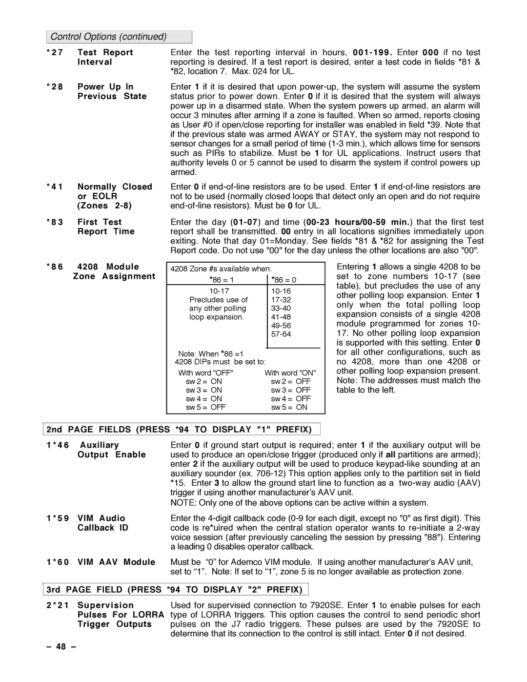
* 8 6 4208 | Module |
Zone | Assignment |
4208 Zone #s available when:
*86 = 1 |
| *86 = 0 |
| |
|
| |||
Precludes use of |
|
| ||
any other polling |
|
| ||
loop expansion. |
|
| ||
|
|
| ||
|
|
| ||
| Ê |
| ÊÊÊÊÊÊÊÊÊÊÊÊÊÊÊÊÊÊÊÊ |
|
Note: When *86 =1
4208 DIPs must be set to:
With word "OFF" | With word "ON" | |
sw 2 | = ON | sw 2 = OFF |
sw 3 | = ON | sw 3 = OFF |
sw 4 | = ON | sw 4 = OFF |
sw 5 | = OFF | sw 5 = ON |
Entering 1 allows a single 4208 to be set to zone numbers
17.No other polling loop expansion is supported with this setting. Enter 0 for all other configurations, such as no 4208, more than one 4208 or other polling loop expansion present. Note: The addresses must match the table to the left.
2nd PAGE FIELDS (PRESS *94 TO DISPLAY "1" PREFIX)
1 * 4 6 Auxiliary | Enter 0 if ground start output is required; enter 1 if the auxiliary output will be | ||
| Output Enable | used to produce an open/close trigger (produced only if all partitions are armed); | |
|
| enter 2 if the auxiliary output will be used to produce | |
|
| auxiliary sounder (ex. | |
|
| *15. Enter 3 to allow the ground start line to function as a | |
|
| trigger if using another manufacturerÕs AAV unit. | |
|
| NOTE: Only one of the above options can be active within a system. | |
1 * 5 9 | VIM Audio | Enter the | |
| Callback ID | code is re*uired when the central station operator wants to | |
|
| voice session (after previously canceling the session by pressing "88"). Entering | |
|
| a leading 0 disables operator callback. | |
1 * 6 0 | VIM AAV Module | Must be Ò0Ó for Ademco VIM module. If using another manufacturerÕs AAV unit, | |
|
| set to Ò1Ó. Note: If set to Ò1Ó, zone 5 is no longer available as protection zone. | |
|
| ||
3rd PAGE FIELD (PRESS *94 TO DISPLAY "2" PREFIX) |
| ||
2 * 2 1 Supervision | Used for supervised connection to 7920SE. Enter 1 to enable pulses for each | ||
| Pulses For LORRA | type of LORRA triggers. This option causes the control to send periodic short | |
| Trigger Outputs | pulses on the J7 radio triggers. These pulses are used by the 7920SE to | |
|
| determine that its connection to the control is still intact. Enter 0 if not desired. | |
Ð 48 Ð |
|
|
|