Page
Page
User Guide
Copyright and License
Table of contents
O Configuration
Managing the printer
Maintenance
Appendix a Working with memory and print server cards
Vii
Viii
Printer basics
Quick access to printer information
Where to look for more information
Setting up the printer
World Wide Web links
Using the printer
Enww
HP Color LaserJet 5500n Europe only
Printer configurations
HP Color LaserJet
HP Color LaserJet 5500dn
HP Color LaserJet 5500dtn
HP Color LaserJet 5500hdn
Printer features
Features
Supported paper weights and sizes
Accessories
Paper handling
Connectivity
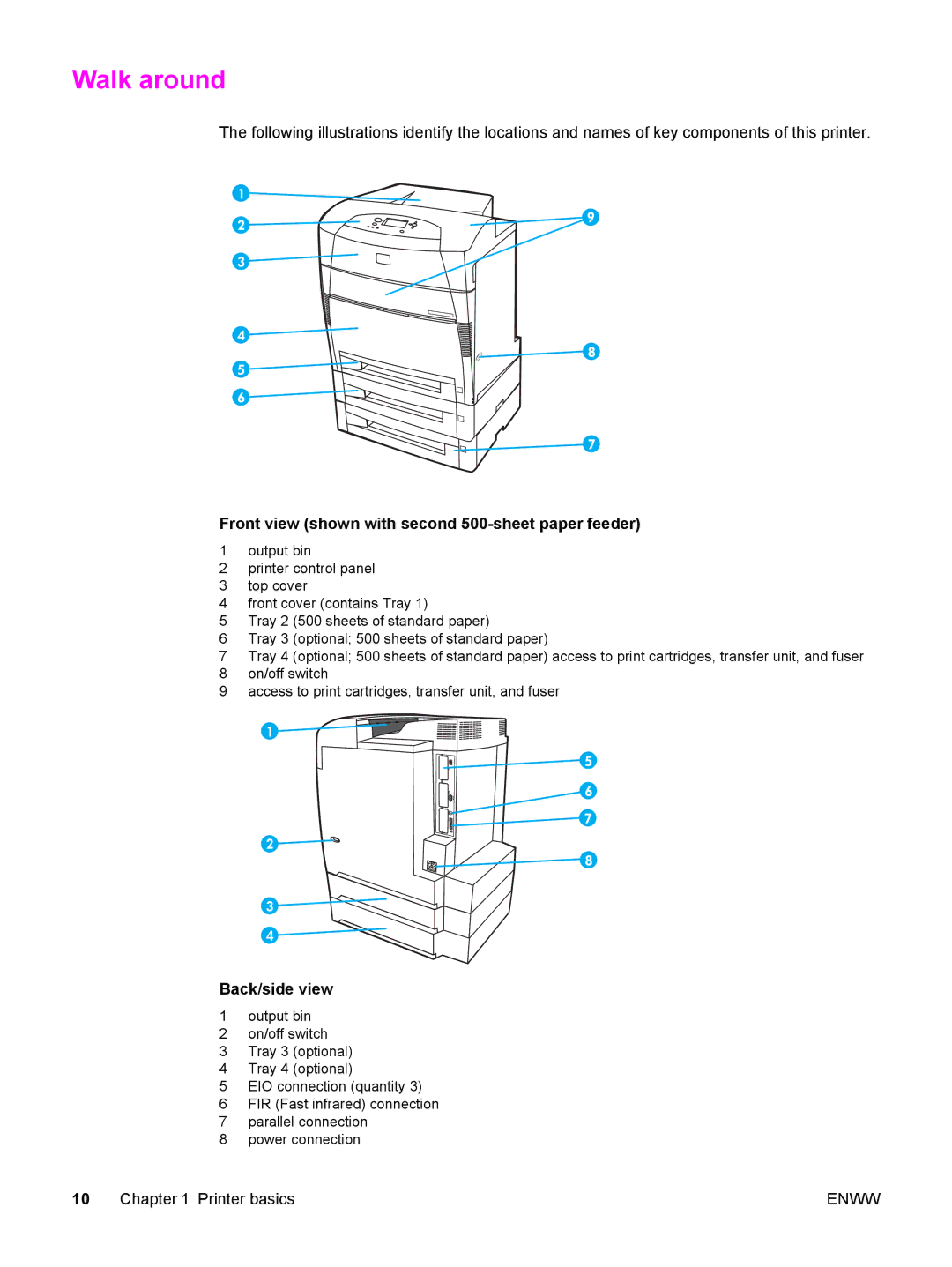
Back/side view
Walk around
Front view shown with second 500-sheet paper feeder
Printer software
Printer drivers
Operating system PCL 5c
PCL
Additional drivers
HP Web Jetadmin
Software for networks
Utilities
Embedded Web server
Network administrator
Other components and utilities
Windows
Macintosh OS
Print media specifications
Supported paper weights and sizes
Tray Dimensions Weight or thickness Capacity
Tray 1 paper sizes
Weight or thickness Capacity
Tray 2 and optional Trays 3 and 4 paper sizes1
Automatic 2-sided printing duplexing1
A4, Letter-R, A4-R
B5, B5-R, A5, A5-R By 17, A3 Standard tough paper
JIS B5, B5-R, A5, A5 11 by 17, A3 Minimum size tough
Enww
Control panel
Control panel buttons and lights
Control panel overview
Display
Accessing the control panel from a computer
Printer display
Control panel buttons
Button name Function
Interpreting control panel indicator lights
Control panel indicator lights
Indicator
Off Flashing
Control panel menus
Getting started basics
To access the menus
Menu hierarchy
Retrieve job menu for printers with a hard disk
Information menu
Configure device menu
Paper handling menu
Diagnostics menu
Description
Retrieve job menu for printers with a hard disk
Menu item
Supplies Status
Information menu
Menu item Description
Paper weights and sizes for a
Weights and sizes for a
Paper handling menu
Menu item Value Description Tray 1 Size
Configure device menu
Copies Default Paper Size
Print PS Errors OFF
Printing menu
System setup menu
Adjust Tray
Print quality menu
List of available modes
See Job held timeout for more information
See PowerSave Time for more information
100
See Job storage limit for more information
Menu
Resets menu
None
Diagnostics menu
Changing printer control panel configuration settings
Job held timeout
To set the job held timeout
Job storage limit
Tray behavior options use requested tray and manually feed
To set use requested tray
To set manually feed prompt
Press to select Manually Feed Prompt
PowerSave Time
To set PowerSave Time
To disable/enable PowerSave
Or to select Always or Unless Loaded
Personality
Clearable warnings
To set the personality
To set the clearable warnings
Auto continue
Supplies low
To set the auto continue
To set supplies low reporting
Jam recovery
To set jam recovery response
Language
To select language
Enww
Using the printer control panel in shared environments
Configuration
Configuring TCP/IP parameters using Bootp or Dhcp
Network configuration
Configuring TCP/IP parameters
Setting an IP address
Setting the subnet mask
Setting the default gateway
To select Config Method
To highlight Manual Settings
To select Manual Settings
Setting the syslog server
Setting the idle timeout
Setting the link speed
Disabling network protocols optional
To disable IPX/SPX
To disable AppleTalk
To disable DLC/LLC
Parallel configuration
Parallel port connection
Enhanced I/O EIO configuration
HP Jetdirect print servers
Available enhanced I/O interfaces
NetWare networks
UNIX/Linux networks
Windows and Windows NT networks
AppleTalk networks
Enww
Printing tasks
Precedence for print settings software
Controlling print jobs
Source
Type and Size
Controlling print jobs
Paper that may damage the printer
Selecting print paper
Paper to avoid
Selecting print paper
Configuring Tray 1 type
Configuring input trays
Configuring Tray 1 size
Tray 2, Tray 3, or Tray 4 custom paper
Tray 2, Tray 3, or Tray 4 detectable standard paper size
Tray 2, Tray 3, or Tray 4 paper type
Dimension
Unit of measure
Loading paper into Tray
Tray 2, Tray 3, or Tray 4 nondetectable standard sizes
Printing from Tray 1 multipurpose tray
Printing envelopes from Tray
To load envelopes into Tray
Printing envelopes
Printing from Tray 2, Tray 3, and Tray
Address type Left margin Top margin
Cause jams in the printer
Enww
Enww
Enww
Printing on special media
Transparencies
Glossy paper
Colored paper
Labels
Heavy paper
Recycled paper
HP LaserJet Tough paper
Preprinted forms and letterhead
Control panel settings for automatic 2-sided printing
Sided duplex printing
Options for binding 2-sided printing jobs
Manual 2-sided printing
Special printing situations
Printing a different first
Printing on custom-size paper
Stopping a print request
Job retention features
Storing a print job
Quick copying a job
Proofing and holding a job
Printing a private job
Private jobs
Deleting stored jobs
Deleting a private job
Setting up to print with Macintosh computers
Printing with the optional HP Fast InfraRed Receiver
Printing a job
Interrupting and resuming printing
Managing memory
Memory, see Working with memory and print server cards
Managing the printer
Configuration
Press to select Print Configuration
Printer information pages
Menu map
To print the supplies status
Supplies status
Usage
Demo
File directory
PCL or PS font list
Event log
Print quality troubleshooting pages
Using the embedded Web server
To access the embedded Web server using a network connection
Settings tab
Information tab
Networking tab
Other links
Using Printer Status and Alerts
To choose which status messages appear
To view status messages and information
Color
Using color
HP ImageREt
Paper selection
Color options
Printing in four-colors Cmyk
Cmyk ink set emulation PostScript only
Automatic or manual color adjustment
Managing color
Print in Grayscale
Manual color options
Managing color
Matching colors
PANTONE* color matching Swatch book color matching
Maintenance
101
Managing the print cartridge
Using the printer control panel
Print cartridge life expectancy
Checking the print cartridge life
Press to highlight Print Supplies Status
Using HP Web Jetadmin
Changing print cartridges
To change the print cartridge
Enww
Color or Incorrect Supplies
Supply replacement guidelines
Replacing supplies
Locating supplies
Supply item locations
Making room around the printer for replacing supplies
Approximate replacement intervals for supplies
Supplies replacement clearance diagram
Software Information location
Configuring e-mail alerts
See Using printer Status and Alerts for directly
To clean the OHT sensor
Periodic cleaning
When to clean the OHT sensor
Enww
Problemsolving
113
Basic troubleshooting checklist
Factors affecting printer performance
Error messages
Critical error messages
Control panel message types
Status messages
Control panel messages
Control panel messages
JOB Name
Chosen Personality not Available
CPR Sensor OUT of Range
JOB Name Disk Device Failure
Disk File Operation Failed
Disk File System is Full
EIO Disk
Flash Device Failure
Flash File Operation Failed
Flash File System is Full
Install Color Cartridge
For help press Install fuser Description Recommended action
Incorrect Color Cartridge
Insert Tray
Load Tray Type Size
Install Transfer Unit
Load Tray X Type Size
Manually Feed Type Size
To continue press
NON HP Cartridge Detected NON HP Cartridge in USE
Order Color Cartridge
Xxxx Pages Left
Order Fuser KIT
Xxxx Pages Left For menus press
Xxxx Pages Left To continue press
Control panel message Order Supplies For menus press
Ready
Order Supplies
For status press
Configuration
Calibration
Demo
Event LOG
Registration
Usage
Reinstall Color Cartridge
Reinstall Supplies
Cartridge Motor
Replace Color Cartridge
New fuser kit?
Server. See Using the embedded Web
Resend upgrade
Transfer Motors
Tray X Contains Unknown Media Tray X Empty Type Size
Tray X Open
Tray Type Size
To change type Press Description Recommended action
USE INSTEAD? Tray Xtype Size
10.XX.YY Supplies Error
Tray X Type Size
Enww
13.XX.YY JAM in Tray
For help press Description
JOB Interrupted
13.XX.YY.DUPLEX JOB Interrupted
Insufficient Memory
Parallel I/O
Unexpected Size in Tray X For help press
Control panel message Description Recommended action
Serial I/O
Printer Error
To continue Turn off then on 52.X
Cancel JOB
Permanent Storage Error
Permanent Storage Full
8X.YYYY EIO Error
Xxxx
Paper jams
Paper jam recovery
To disable paper jam recovery
Paper jams
Issue Cause
Solution
Common causes of paper jams
Common causes of paper jams1
Issue Cause Solution
Common causes of paper jams
Clearing paper jams
Jam in Tray 1 or Tray
Clearing paper jams
Enww
Enww
Jam in Tray 3 or Tray
Enww
Enww
Enww
Flush with the paper guides
Jams in the top cover
Jam in the top cover
Enww
Enww
Close the transfer unit and front cover Close the top cover
Jam in paper input path or paper path
Enww
Completely closed
Jam in duplex path
Enww
Close the transfer unit and front cover Close the top cover
Paper handling problems
Paper handling problems
Exclusively
Printer feeds incorrect
Size
Paper does not feed
Automatically
Issue
Paper does not feed from Trays 2, 3, or
Transparencies or glossy paper
Will not feed
Envelopes jam or will not feed in the printer
Cause Solution
Configuring input trays
Enww
No display message
Printer response problems
Printer response problems
Configuration settings
See Changing printer control panel configuration settings
Printer is on, but nothing prints
See Control panel messages
See Parallel configuration or
Configuration
Printer is on but is not receiving data
Enhanced I/O EIO
Unable to select the printer from the computer
Printer control panel problems
Printer control panel problems
Color printing problems
Color printing problems
Grayscale is selected
Driver
Printed colors do not match screen colors
Incorrect printer output
Incorrect printer output
Incorrect fonts are printed
Erratic, missing characters or
Panel
Memory error message
Guidelines for printing with different fonts
Software application problems
Software application problems
Overhead transparency defects
Print quality troubleshooting
Print quality problems associated with paper
Print quality problems associated with maintenance
Print quality problems associated with the environment
Print quality problems associated with jams
Printing a configuration
Working with memory
Print server cards
Printer memory
Installing memory and font DIMMs
To install memory and font DIMMs
Installing memory and font DIMMs
Enww
Enww
Checking Dimm installation
To enable memory for Windows
To check Dimm installation
Enabling the language font Dimm
Installing an HP Jetdirect print server card
To install an HP Jetdirect print server card
Enww
Enww
Enww
193
Supplies and accessories
Spare parts and supplies availability
Supplies, accessories, and part numbers
Part Part number Type/size
195
Package
Service and Support
Hewlett-Packard limited warranty statement
Appendix C Service and Support
Limited warranty for print cartridge life
Transfer unit and fuser warranty
Extended warranty
HP maintenance agreements
On-site service agreements
Enww
Printer specifications
Physical dimensions
Electrical specifications
203
Operating environment specifications
Activity level Operator 1m Bystander 1m Sound power
Acoustic emissions
Environment Allowed
Regulatory information
FCC regulations
Environmental product stewardship program
Material Safety Data Sheet Msds For more information
Material restrictions
Enww
Conforms to the following Product Specifications
Declaration of Conformity
Safety statements
Laser safety
Canadian DOC regulations
EMI statement Korea Vcci statement Japan
Laser Statement for Finland
Luokan 1 laserlaite
Enww
Bootp
Glossary
IPX/SPX
PJL
ROM
Symbols/Numerics
Index
Language
Enww
Enww