The VSDs in this scenario are mapped to the raw logical volumes lv_X and lv_Y. Node X is a client of Node Y’s VSD, and vice versa. Node X is also a direct client of its own VSD (lv_X), and Node Y is a direct client of VSD lv_Y. VSD configuration is flexible. An interesting property of the architecture is that a node can be a client of any other node’s VSD(s), with no dependency on that client node owning a VSD itself. You could set up three nodes with powerful I/O capacity to be VSD servers, and ten application nodes, with no disk other than for AIX, PSSP, and the application executables, as clients of the VSDs on these server nodes.
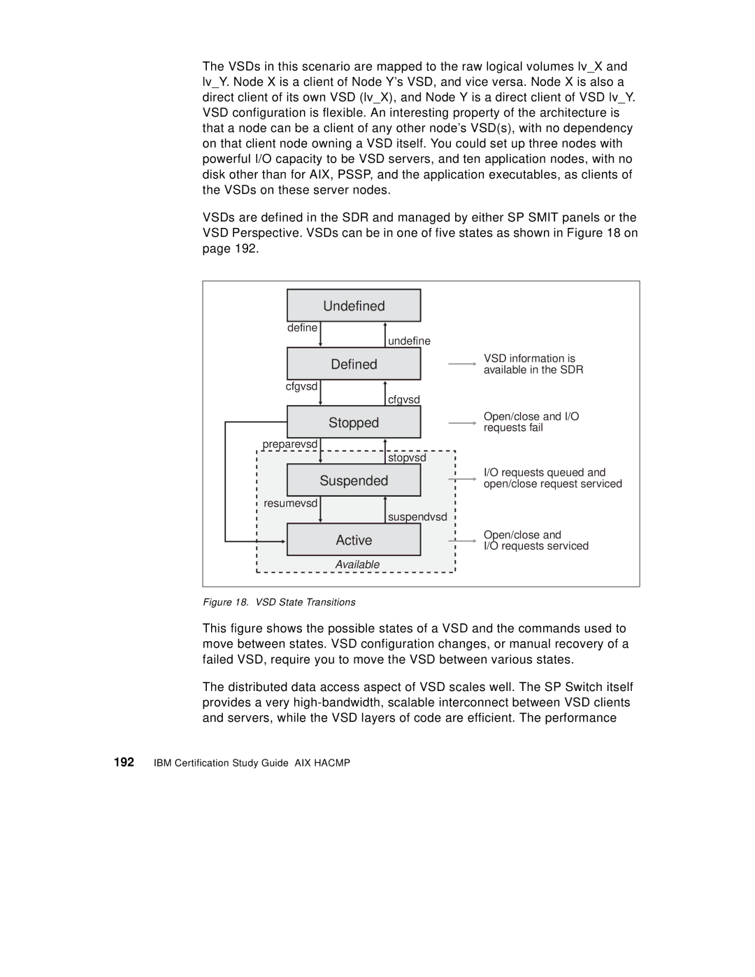
VSDs are defined in the SDR and managed by either SP SMIT panels or the VSD Perspective. VSDs can be in one of five states as shown in Figure 18 on page 192.
Undefined
define![]() undefine
undefine
Defined
cfgvsd![]() cfgvsd
cfgvsd
Stopped
preparevsd
stopvsd
Suspended
resumevsd
suspendvsd
Active
Available
VSD information is available in the SDR
Open/close and I/O requests fail
I/O requests queued and open/close request serviced
Open/close and
I/O requests serviced
Figure 18. VSD State Transitions
This figure shows the possible states of a VSD and the commands used to move between states. VSD configuration changes, or manual recovery of a failed VSD, require you to move the VSD between various states.
The distributed data access aspect of VSD scales well. The SP Switch itself provides a very
