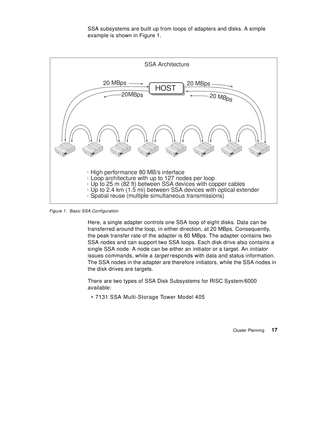
SSA subsystems are built up from loops of adapters and disks. A simple example is shown in Figure 1.
SSA Architecture
20
MBps | |
| HOST |
2 | 0MB |
ps | |
20
M
B
p |
|
s |
|
20 | M |
| B |
| p |
| s |
lHigh performance 80 MB/s interface
lLoop architecture with up to 127 nodes per loop
lUp to 25 m (82 ft) between SSA devices with copper cables
lUp to 2.4 km (1.5 mi) between SSA devices with optical extender l Spatial reuse (multiple simultaneous transmissions)
Figure 1. Basic SSA Configuration
Here, a single adapter controls one SSA loop of eight disks. Data can be transferred around the loop, in either direction, at 20 MBps. Consequently, the peak transfer rate of the adapter is 80 MBps. The adapter contains two SSA nodes and can support two SSA loops. Each disk drive also contains a single SSA node. A node can be either an initiator or a target. An initiator issues commands, while a target responds with data and status information. The SSA nodes in the adapter are therefore initiators, while the SSA nodes in the disk drives are targets.
There are two types of SSA Disk Subsystems for RISC System/6000 available:
• 7131 SSA
