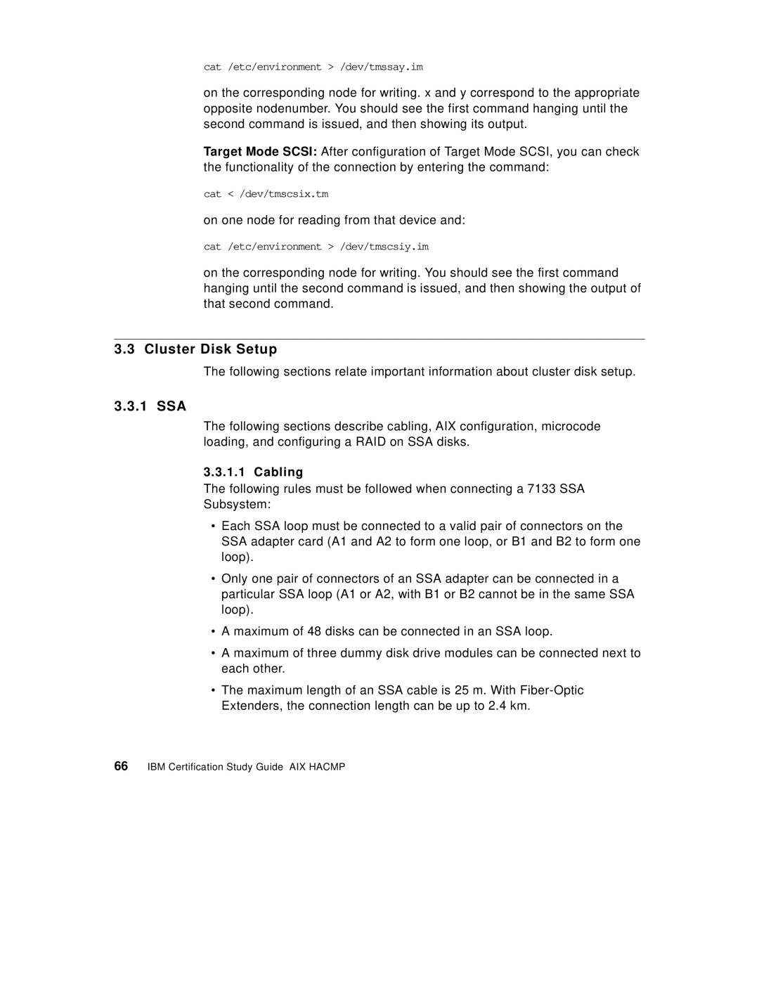
cat /etc/environment > /dev/tmssay.im
on the corresponding node for writing. x and y correspond to the appropriate opposite nodenumber. You should see the first command hanging until the second command is issued, and then showing its output.
Target Mode SCSI: After configuration of Target Mode SCSI, you can check the functionality of the connection by entering the command:
cat < /dev/tmscsix.tm
on one node for reading from that device and:
cat /etc/environment > /dev/tmscsiy.im
on the corresponding node for writing. You should see the first command hanging until the second command is issued, and then showing the output of that second command.
3.3 Cluster Disk Setup
The following sections relate important information about cluster disk setup.
3.3.1 SSA
The following sections describe cabling, AIX configuration, microcode loading, and configuring a RAID on SSA disks.
3.3.1.1 Cabling
The following rules must be followed when connecting a 7133 SSA
Subsystem:
•Each SSA loop must be connected to a valid pair of connectors on the SSA adapter card (A1 and A2 to form one loop, or B1 and B2 to form one loop).
•Only one pair of connectors of an SSA adapter can be connected in a particular SSA loop (A1 or A2, with B1 or B2 cannot be in the same SSA loop).
•A maximum of 48 disks can be connected in an SSA loop.
•A maximum of three dummy disk drive modules can be connected next to each other.
•The maximum length of an SSA cable is 25 m. With
