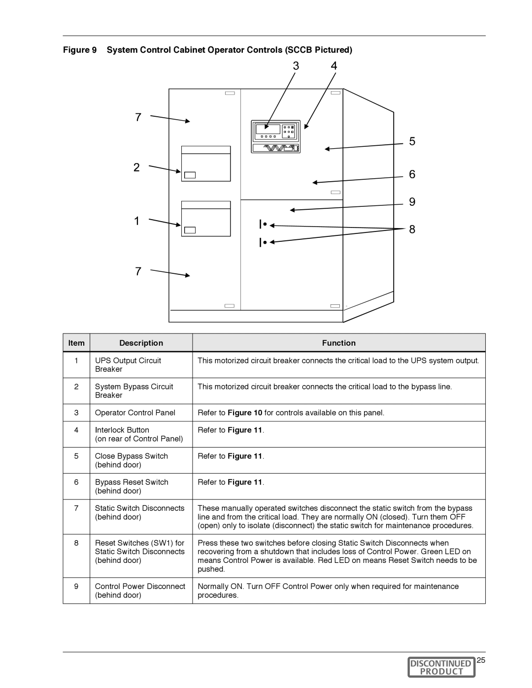
Figure 9 System Control Cabinet Operator Controls (SCCB Pictured)
Item | Description | Function |
1 | UPS Output Circuit | This motorized circuit breaker connects the critical load to the UPS system output. |
| Breaker |
|
2 | System Bypass Circuit | This motorized circuit breaker connects the critical load to the bypass line. |
| Breaker |
|
3 | Operator Control Panel | Refer to Figure 10 for controls available on this panel. |
|
|
|
4 | Interlock Button | Refer to Figure 11. |
| (on rear of Control Panel) |
|
5 | Close Bypass Switch | Refer to Figure 11. |
| (behind door) |
|
6 | Bypass Reset Switch | Refer to Figure 11. |
| (behind door) |
|
7 | Static Switch Disconnects | These manually operated switches disconnect the static switch from the bypass |
| (behind door) | line and from the critical load. They are normally ON (closed). Turn them OFF |
|
| (open) only to isolate (disconnect) the static switch for maintenance procedures. |
8 | Reset Switches (SW1) for | Press these two switches before closing Static Switch Disconnects when |
| Static Switch Disconnects | recovering from a shutdown that includes loss of Control Power. Green LED on |
| (behind door) | means Control Power is available. Red LED on means Reset Switch needs to be |
|
| pushed. |
9 | Control Power Disconnect | Normally ON. Turn OFF Control Power only when required for maintenance |
| (behind door) | procedures. |
Operation 25