Technical Product Manual DCT1900 System
LZB 119 2663 R8
Where to find what
Preface
What this manual describes
Who should use this manual
VII
Safety and Regulatory Information
Section
Technical Product Manual DCT1900
Table of Contents
Safety-DCT1900/R8/mw
Safety
General
Safety-DCT1900/R8/mw
Standards and Regulations
Radio Equipment Handsets and Base Stations
Technical Product Manual DCT1900
Technical Product Manual DCT1900
Technical Product Manual DCT1900
Protection against Electrostatic Discharge ESD
ESD Handling
Protect ESD Sensitive Devices
System Description
Technical Product Manual DCT1900
Introduction
System Overview
Hardware Building Blocks
Radio Exchange Boards
Other System Aspects
Introduction
Technical Product Manual DCT1900
Digital Phone Set Features
System Overview
DCT1900 Network Signalling Summary
System Overview DCT1900 Standalone Environment
System Overview DCT1900 Mobility Environment
Operational Concepts
Operational Environment
Environmental External Dependencies
Functional External Dependencies
System Architecture
Synchronization Topology
Registration
Start of Registration
Registration Successful
Registration Failures
Authentication
Inter System Handover DCT1900 Mobility Configuration Only
Roaming DCT1900 Mobility Configuration Only
De-registration
Roaming and Handover Handling by the Portable Telephone
Unlocked Situation
Locked Situation
Environment Scanning by the Portable Telephone
System Status
Roaming
Voluntary Intra System Roaming
Voluntary Inter System Roaming
User Functions
Standalone Digital Line Interface
Standalone Analog Interface and T1 CAS Digital Interface
Technical Product Manual DCT1900
Hardware Building Blocks
Radio Exchange
Base Stations
Portable Telephones
Radio Exchange Boards
REX-BRD0007 Standalone only
Speech Link Unit SLU REX-BRD0015 or Rofnb 157 16/1
SLU
Speech Processing Unit SPU-S REX-BRD0017 or Rofnb 157 16/3
SPU
CLU/CLU-S
DTU-E1 CCS
CAS REX-BRD0002 or 2/ROFNB 157 13/1
DTU-E1 -CAS
DTU-T1 CAS
DTU-T1 CCS
LTU
Digital Line Unit DLU REX-BRD0023 Basic Board
DLU
Modular Cabinet Connection Board-MCCB Roanb 101
Radio
Installation and Maintenance
Other System Aspects
Statistics
Traffic Limitations of the System
Characteristics
Numbering Conventions
Modular Cabinet number option Cabinet with CPU board
Base Station Numbering
Product Specifications
Technical Product Manual DCT1900
Batteries
Chargers
Cabinets
System Boards
Power Supply Units
Accessories-Portable Telephone
Firmware on Eprom
Cables
Technical Product Manual DCT1900
Portable Telephones
DT600 Portable Telephone KRC 101 1372 no antenna, Darla Dis
Ringer Output
DT620 Portable Telephone KRC 101 1374 no antenna, Dixie Dis
User Interface
9p23 Portable Telephone Messenger 9p23-AAB4
9p23 Portable Telephone Medic 9p23-BAB4
9p23 Portable Telephone Mark II Medic 9p23-DAB4
9p23 Portable Telephone Mark II Messenger 9p23-CAB4
9p23 Programmer Set
Base Stations
Base Station KRC 101
Base Station Cable
Maximum Cable Length feet
Tolerances
Straight Antenna KRE 101 1733/55
Right Angle Antenna KRE 101 1750/55
Adapter Mounting Plate Kit NTM 201
Mounting Kits Outdoor/Wall Mounting Kit NTM 201
Indoor/Ceiling Mounting Kit NTM 201
Batteries for the DT600 High Capacity NiMH BKB 193
Vibrating Battery, NiMH BKB 191
Batteries
Ultra-Slim Line NiMH Battery BKB 193 105/75
Medic Battery
Batteries for the 9p23 Messenger Battery
Messenger Battery with headset connection
Medic Battery with headset connection
Chargers for the DT600 Desk Multi-Charger Kit NTM 201
Rapid Battery Charger Kit BML 162 1016/72 Dis
Chargers
Chargers for the DT620 Rapid Charger BML 162
Rapid Desk Charger BML 162
Rack Charger Kit NTM 201
Desktop Charging Cradle BML 162 112/04
Docking Station DPY 901
4 9p23 Modular Rack Charger US Power Module
Chargers for the 9p23 1 9p23 Messenger Desktop Charger
2 9p23 Medic Desktop Charger
3 9p23 Non-Modular Rack Charger AWS1068
5 9p23 Modular Rack Charger 4 Slot Charging Module RC23
Technical Product Manual DCT1900
Modular Cabinet Connection Board, Mccb Roanb 101
Cabinets
Modular Cabinet Backplane Roanb 101
Installation Set Sync Port CPU
SDB
System Boards
Digital Trunk Specification
Environment
Central Processing Unit CPU2-REX-BRD9033, REX-BRD9034
Sync
Speech Link Unit, SLU REX-BRD0015 or Rofnb 157 16/1
Fusing
Transport Data Rate 384 kbit/s General Specifications
Speech Processing Unit, SPU-S REX-BRD0017 or Rofnb 157 16/3
Cell Link Unit, CLU REX-BRD0014 or Rofnb 157 11/2
Cell Link Unit, CLU-S REX-BRD0016 or Rofnb 157 16/2
Line Termination Unit, LTU REX-BRD0007 or Rofnb 157 02/06
Line Termination Unit , LTU2 REX-BRD0019A
Standard 712 Method Kbit/s A-law or μ−law PCM‘
Digital Line Specification
Firmware on Eprom
LTU Firmware REX-SW0012 or RYS 105
13 LTU2 Firmware REX-LTU2FW01/1H
Power Supply Units
Technical Product Manual DCT1900
Cables
Cables for Modular Cabinet
DTU-T1/MDF Twisted Pair Cable Trsnb 101 50 AWS1034
LTU/MDF Cable Set NTM/TSRNB 101
DLU/PBX Cable Set AWS1019
Pabx Cable E1 Tsrnb 101
DT620 Portable Telephone Programming Cable KRY 101 1135/10
DLU Programming Cable AWS1027
Technical Product Manual DCT1900
Feature and Phonebook Download Tool AWS1092
Minimum PC configuration
Software
Csmw Software Kit, Utam REX-MTC9023
Site Survey Tool Configuration Manager LZY 213
Accessories-Portable Telephone
Accessories for the DT600
Accessories for the DT620
Accessories for the 9p23
Headsets and Adapters
11-4
Configuration Directions
Technical Product Manual DCT1900
Base Station Powering
Limitations of the System
Base Station Planning
Traffic Capacity of the System
Technical Product Manual DCT1900
Configuration Directions, Introduction
Technical Product Manual DCT1900
Limitations of the System
Modular Cabinets
Synchronization Topology
Modular Cabinet Powering Restrictions
A r d T y p e + 1 2
Technical Product Manual DCT1900
Absorption and Reflection
Base Station Planning
Total Area Coverage
Departmental Differences
Architecture
Site Survey
Measurement of Typical Cell Size
Base Station Count Estimating
Atotal
Technical Product Manual DCT1900
Base Station Powering
Powering Base Stations by a Remote Power Supply
Power Limited Length of Base Station Cable
Data Limited Length of the Base Station Cable
Powering Base Stations via the Modular Cabinet
1 -48V External Source Powering
Tables
How the Values in the Tables are Calculated
⎛ U
Tables
CLU SLU
Cable
AWG 0.5 mm wire size ∅
Power Consumption from Power Supply Related to Cable Length
Example
Power Consumption Related to Cable Length
Technical Product Manual DCT1900
Traffic Capacity of the System
Traffic Capacity of the Radio Exchange
Traffic Capacity of the Base Stations
Erlang Values Expressed in Call-Minutes
Traffic Capacity of the System
Technical Product Manual DCT1900
Relation between Parts
Radio Exchange
Power Supplies
Cables
Installation Instructions
Technical Product Manual DCT1900
Modular Cabinet Installation Steps
Central Processing Unit CPU REX-BRD0004 or 2/ROFNB 157 19/2
Central Processing Unit CPU2 REX-BRD9033, REX-BRD9034
Cell Link Unit CLU REX-BRD0014 or Rofnb 157 11/2
Cell Link Unit CLU-S -REX-BRD0016 or Rofnb 157 16/2
Digital Trunk Unit DTU-E1 REX-BRD0002 or 2/ROFNB 157 13/1
Base Station KRC 101 1371
Modular Cabinet Power Cabling
Modular Cabinet Connection Board Mccb Roanb 101 28
Modular Cabinet CPU Cabling
Modular Cabinet CLU/SLU to Base Station Cabling
Modular Cabinet LTU Cabling
Modular Cabinet DLU Cabling
Use of TDR
Modular Cabinet Cables
Technical Product Manual DCT1900
Introduction
Technical Product Manual DCT1900
Safety and Regulatory Information
General
Environmental Requirements
ESD Socket
Miscellaneous Items
Switch Room
Equipment Verification
Modular Cabinet Installation Steps
Recommended Board Positions
Main Steps of Installation
Switching On/Off
Unpacking
Charging Portable Telephone Batteries
Labels
Position of the Board Position Label
Connector Positions and Examples of Cable Labelling
Technical Product Manual DCT1900
Contents of the Box
Modular Cabinet REX-BAS9021 or Bdvnb 101 01/2
Installation Area for the Modular Cabinets
Installation of the Modular Cabinets
Parts of the Modular Cabinet
Bottom view
Fuse Wrist strap connector Power on/off switch
Pre-mounting of a Modular Cabinet in a One Cabinet System
Pre-mounting of Modular Cabinets in a Multi Cabinet System
Placement of the Shielding Gaskets Distance adjustment plate
Torx screwdriver nr
Sync port installation set Ntmnb 101
Mounting the Modular Cabinets to the Wall
Connection to Protective Ground
Ground Plate
Connection of Wrist Strap for ESD
Modular Cabinet must be connected to protective ground
Interconnecting Modular Cabinets
10 Backplane of Modular Cabinet
Add a Cabinet
Procedure
Placing the Securing Bar
Technical Product Manual DCT1900
Technical Product Manual DCT1900
Do not mount the new cabinet
Schedule Down Time
Technical Product Manual DCT1900
Technical Product Manual DCT1900
Maintenance
Central Processing Unit CPU REX-BRD0004 or 2/ROFNB 157 19/2
Board Description
Functionality
Strap Settings
Synchronization Topology
When master Accepting framing clock from DTU or DLU source
Providing framing clock to DTU or DLU source
LEDs
Connectors
Reset Button
Installation
Use ESD precautions
Fpga Installation
CPU-REX-BRD0004 or 2/ROFNB 157 19/2
Technical Product Manual DCT1900
System Boards
General Specifications
Central Processing Unit CPU1 REX-BRD0004 or 2/ROFNB 157 19/2
Speech Link Unit, SLU REX-BRD0015 or Rofnb 157 16/1
Speech Processing Unit, SPU-S REX-BRD0017 or Rofnb 157 16/3
Cell Link Unit, CLU-S REX-BRD0016 or Rofnb 157 16/2
Line Termination Unit, LTU REX-BRD0007 or Rofnb 157 02/06
Line Termination Unit , LTU2 REX-BRD0019A
Standard 712 Method Kbit/s A-law or μ−law PCM‘
Digital Line Specification
Cell Link Unit CLU REX-BRD0014 or Rofnb 157 11/2
Straps
CLU REX-BRD0014 or Rofnb 157 11/2
Power Distribution on the CLU
Install-DCT1900/R8/mw
Cell Link Unit CLU-S -REX-BRD0016 or Rofnb 157 16/2
CLU-S REX-BRD0016 or Rofnb 157 16/2
Power Distribution on the CLU-S
Technical Product Manual DCT1900
Speech Link Unit SLU REX-BRD0015 or Rofnb 157 16/1
SLU REX-BRD0015 or Rofnb 157 16/1
Base Station Power Distribution on the SLU
Technical Product Manual DCT1900
Straps and Connectors
Speech Processing Unit SPU-S REX-BRD0017 or Rofnb 157 16/3
SPU-S REX-BRD0017 or Rofnb 157 16/3
Digital Trunk Unit DTU-E1 REX-BRD0002 or 2/ROFNB 157 13/1
Straps should be placed in the twisted pair position 120 Ω
Each DTC has its own LEDs
DTC2 DTC1
11-4
Jumpers
Setting of the Jumpers
DTC2
12-4
Red Normally off. Watch-dog LED not significant
13-2
DTU-T1- REX-BRD0021 or 2/ROFNB 157 13/3
13-4
LTU supports 8 two wire analog connections to a PBX
14-2
JP5
CPU Settings
Application.hex Version Download Procedure
Programming
Set-Up
FPGA.mcs Version Download Procedure
DLU REX-BRD0023
Contents of the Box
Power Distribution
Base Station KRC 101
Firmware
LEDs Fig
Status LED Green/Red/Orange Base Station Status
Base Station Cabling
Base Station Cover and Back
Base Station Cable Delay Measurement
Hardware PN Rev Firmware/Software Application Firmware PN
16-5
Installation Criteria
Connecting the Base Station Plug to the Cable
Instructions Ceiling Mount Kit
Base Station Mounting Indoor 16.6.1 Wall Mount
Ceiling Mount
Cut Mounting Clip Adhere plastic spacer to the mounting clip
Ceiling Bracket with Ceiling Clips attached to Base Station
Base Station Mounting to Factory Ceiling I Beams
Mounting Technique
Introduction
Base Station Mounting Outdoor
Outdoor Base Station Mounting Instruction
Building Corner
Mounting Instructions
16-14
Weatherproof Housing Rear view
Weatherproof Housing rear view
16 Mounting Plate Small Pattern
17 Mounting Plate Large Pattern
Modular Cabinet Connection Board Mccb Roanb 101
DTU Cable Ground Strap Settings
Fuses
DTU Coax Cable Ground Strap Settings on Mccb
DTC In/Out Connectors
DTC1, DTC2, DTC3, DTC4
Modular Cabinet Connection Board Mccb Roanb 101
17-6
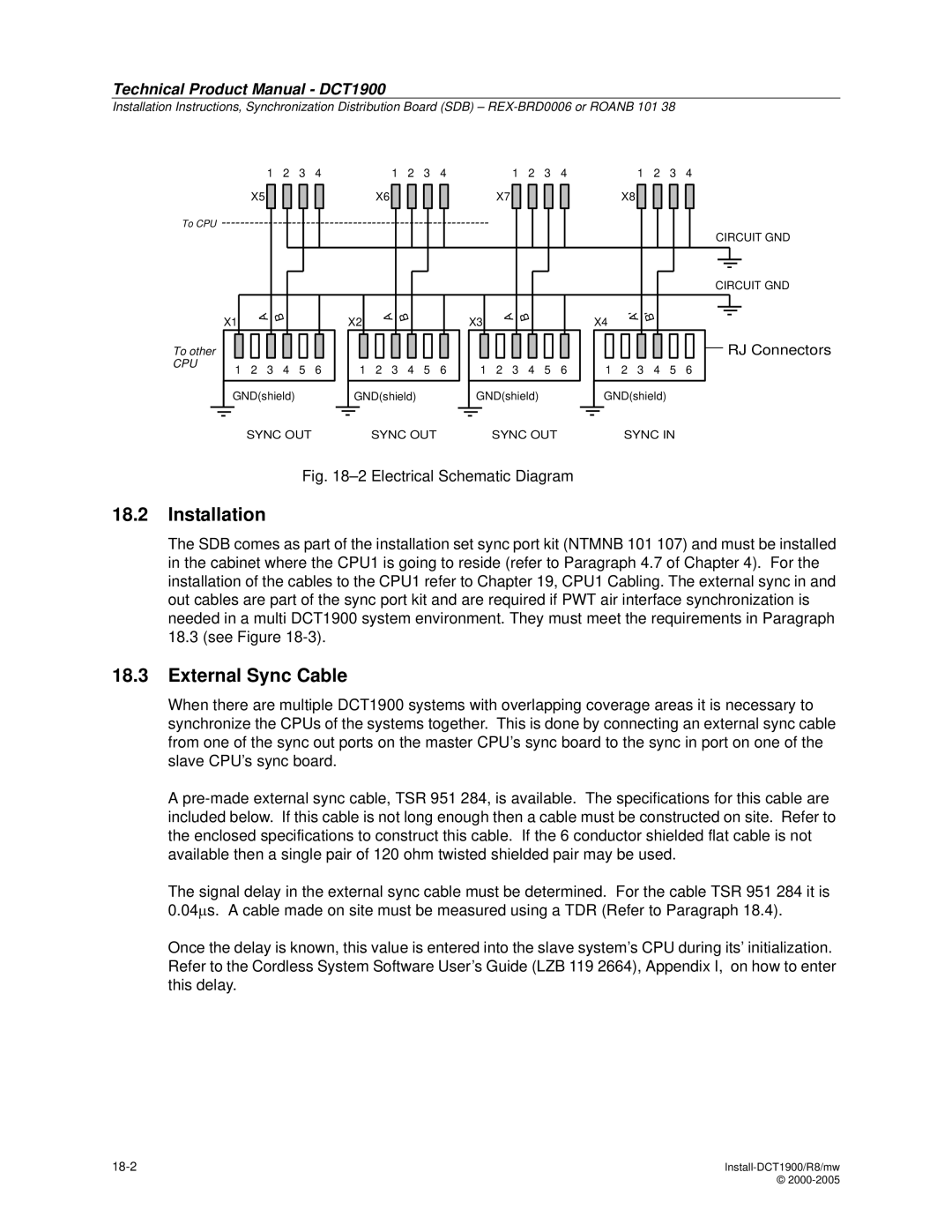
Synchronization Distribution Board REX-BRD0006 or Roanb 101
External Sync Cable
To CPU
Sync Input Cable Delay Measurement
External Sync Cable TSR 951
18-4
Modular Cabinet Power Cabling
Modular Cabinet Bdvnb 101 01/3 R2, R3
Factory Fitted Power Cabling
Power Connection to the Modular Cabinet
Filter Top of Filter
Modular cabinet powered by a -48Vdc PBX power supply
19-5
Mccb
Red
Modular Cabinet REX-BAS9021A/1B
10 Power Connection to the Modular Cabinet
11 Power Connections to Top of Filter
19-11
TS R N B 101
19-13
PW1 PW2 PW3 PW5 PW6PW7 PW-EXT PW4 PW3 PW2
Modular Cabinet CPU Cabling
20.2 CPU1 Cabling
Connections to the Mccb
Connections to the SDB
SDB
Cable Tie Blocks on the Ground Strip
Connection to the PC, Printer, and SMS System
CPU1 Sync Port Pin Connections
Synchronization Data Board SDB replacement Cable AWS1154
Connection to Alarm Device
Connection of the Sync Cable
CPU1 to CPU1 Figure
20.4 CPU2 Cabling
CPU2 Board Connections
Connection to the Sync Cable
CPU2 Sync Port Connector
CPU2 Sync Cable AWS1153
CPU2 to CPU2 More than 2 REs Figure
Mixing CPU1 and CPU2 based Systems
Master Cable Output
CPU1 to CPU2 Connection
10 CPU2 to CPU1, CPU2 Master, CPU1 Slave, Multiple REs
Modular Cabinet CLU/SLU to Base Station Cabling
Ground Strip with Shielding Clamps
Installation of Cables
CLU/SLU to the MDF
Base Station Power
Cabling from the MDF to the Base Station
TOP
This is not Pinned OUT AS a 568A or 568B Connector
Local Powering of a Base Station
Record Keeping
CLC
Identification of the Cable Pairs in NTM/TSRNB 101
CLU to 66 Block Cabling
Red SC1-0 Cicuit
Number Delay Location of Base Station
21-12
Modular Cabinet DTU Cabling
Installation DTU-E1
DTC Connections on the DTU-E1
Installation DTU-T1 CAS or CCS
DTC Connections on the DTU-T1
22-4
Modular Cabinet LTU Cabling
LTU/MDF Cable Connections to the LTU
LTU to 66 Block Cabling
Connector Cable Pair-In Wire Color Signal Name
Modular Cabinet DLU Cabling
DLU Board
Connection to PBX’s
Table -1 Pinout
Determining the Delay of Remote Base Station Cable
Use of TDR
Transmitted and Reflected Pulses
Examples
25-4
Mains Power Cord RPM 113 Power Cable Filter/Switch Trenb 101
Modular Cabinet Cables
Mccb Power Cable Trenb 101
Mccb Power Cable Trenb 101
Power Cable Switch/Fuse Trenb 101
Power Cable Switch/Fuse Trenb 101
Power Cable Switch/Backplane Trenb 101
Power Cable Fuse/Backplane Trenb 101
PC or SMS Cable Tsrnb 101 22D
PC Cable Tsrnb 101 22D
Signal PIN DTR DCD RTS CTS GND
Printer Cable Tsrnb 101
26.8 CPU/MCCB Serial Connection Cable Tsrnb 101
CPU/MCCB Serial Connection Cable Tsrnb 101
Fold back shield 11 .4 Notch
General Alarm Cable Tsrnb 101
General Alarm Cable Tsrnb 101
26.10 CLU/MDF Cable Set NTM/TSRNB 101
10 CLU Cable Connector a
11 CLU Cable Connector B
12 CLU/MDF Cable Set NTM/TSRNB 101
26.11 LTU/MDF Cable Set NTM/TSRNB 101
13 LTU/MDF Cable Set NTM/TSRNB 101
26.12 CLU/MCCB Power Cable Tsrnb 101
26.13 CLU/MDF Cable Set, Long NTM/TSRNB 101
15 CLU/MDF Cable Set NTM/TSRNB 101
16 CLU/MDF Cable Set NTM/TSRNB 101 46 cont’d
26.14 CPU1/SDB Twisted Pair Sync Cable Tsrnb 101
17 CPU1/SDB Twisted Pair Sync Cable Tsrnb 101
18 DTU Twisted Pair Cable E1
19 DTU Twisted Pair Cable T1
20 Wiring Diagram External Sync Cable
Sync Cable TSR 951
26-22
Commissioning
Technical Product Manual DCT1900
Visual Checks
Portable Telephone Test
Radio Coverage Verification
Synchronization Test
Comm-DCT1900/R8/mw
Commissioning, Introduction
Technical Product Manual DCT1900
Synchronization Test
Test
Technical Product Manual DCT1900
Test
Radio Coverage Verification
Base Station Test
Area Coverage Test
Evaluation
Display Layout MER Test
Technical Product Manual DCT1900
Portable Telephone Test
Portable Telephone Test for SMS
Technical Product Manual DCT1900
Availability of all System Boards and Base Stations
Visual Checks
LEDs on the System Boards
Technical Product Manual DCT1900
Radio Exchange Tests
General Alarm
Battery Back-up
Technical Product Manual DCT1900
Maintenance
Technical Product Manual DCT1900
Maintenance Philosophy
Test and Maintenance Software
Fault Signalling
Hapter
Fault Finding Procedures
Service Messages
Part Replacement
Preventive Maintenance
Maintenance Philosophy
Concept of Maintenance
Technical Product Manual DCT1900
Test and Maintenance Software
Error Handling
Board Controllers and Peripherals
Diagnostics
Fault Counters
Test
Maintenance
Error Tables
Testing
Board Power-on Test
Board Test
Board Announcement
Resets
Reset Types
Ack Test
3 24-Hour Test
Reset Table
Relative Counters
Counters for CPU
Counters for Board Controllers
Counters for Peripherals
Reset Counters and Error Tables
Fault Signalling
General Alarm/Service Message
General Alarm Signal
System Service Required
Checking Component Status through Cordless System Manager
Explanation of States
Individual User Complaints
Base Station BS States
DLU Port States
DTU Layer States Layer 1 L1
Common User Complaints
LEDs
LEDs on System Boards
LED
LEDs on CPU
Power LED
LEDs on Base Station
Dynamic Channel Allocation DCA Display Portable Telephone
LED 1
Activating DCA mode
ALL-FP + RSS
Explanation of DCA Service Displays
Link Info
ChannelInf
All-FP+RSS
FP-Info
SysList
TimeSlots
SysOrder
Last Error
MER tests
Service Messages
Service Message Format
Handling Error Messages
How to display messages
Fault Codes
Comment to the Table
Fault Codes in Service Table
Comment to Fault Codes
Service
Part Replacement
General Rules
Replacing a System Board
Replacing the CPU
Replacing a Base Station
Expansion of Modular Cabinet System
Re-positioning Boards
Modular Cabinet Fuses near power switch
Modular Cabinet Fuse near power switch to Backplane
Adding Boards
Fuses
Procedure B
Board Reset
Procedure a
Technical Product Manual DCT1900
Fault Finding Procedures
Symbols used in the Flow Charts
Fault Finding Flowcharts
How Defective Items are Indicated
System Manager Control Service
Yes Adapter When using CLU check related fuse
SDB
Individual User Complaint
No Dial Tone
END
Errors
Corrupted. Re-initialize Portable
Check PC cabling From COM1 via
Technical Product Manual DCT1900
Glossary
Gloss-DCT1900/R8/mw 2000-2005
Glossary
Gloss-DCT1900/R8/mw
Glossary
Rssi