|
| |
G | COM2 | COM2 serial port |
H | COM1 | COM1 serial port |
I | ||
J | Function select | See Configuring Switch and Jumper Settings in Chapter 4 |
| switches | of this User’s Guide. |
K | Dump button | See Configuring Switch and Jumper Settings in Chapter 4 |
|
| of this User’s Guide. |
L | VGA | VGA monitor |
M | Printer | LPT1 |
|
| connector. |
N | PCI slots | Six PCI |
O | Knockouts | Available to route SCSI signals to peripheral boxes. |
P | Knockouts | Available to route SCSI signals to peripheral boxes. |
Q | EISA slots | Four EISA |
R | Power supply status | See Table |
| lamps |
|
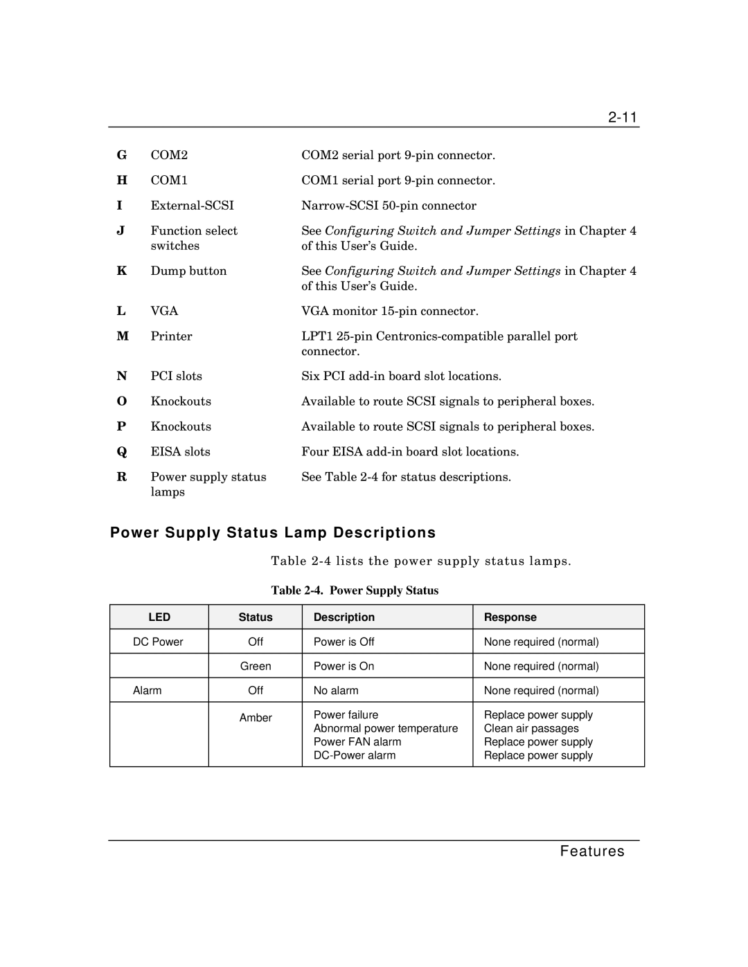
Power Supply Status Lamp Descriptions
Table
Table 2-4. Power Supply Status
LED | Status | Description | Response |
|
|
|
|
DC Power | Off | Power is Off | None required (normal) |
|
|
|
|
| Green | Power is On | None required (normal) |
|
|
|
|
Alarm | Off | No alarm | None required (normal) |
|
|
|
|
| Amber | Power failure | Replace power supply |
|
| Abnormal power temperature | Clean air passages |
|
| Power FAN alarm | Replace power supply |
|
| Replace power supply | |
|
|
|
|