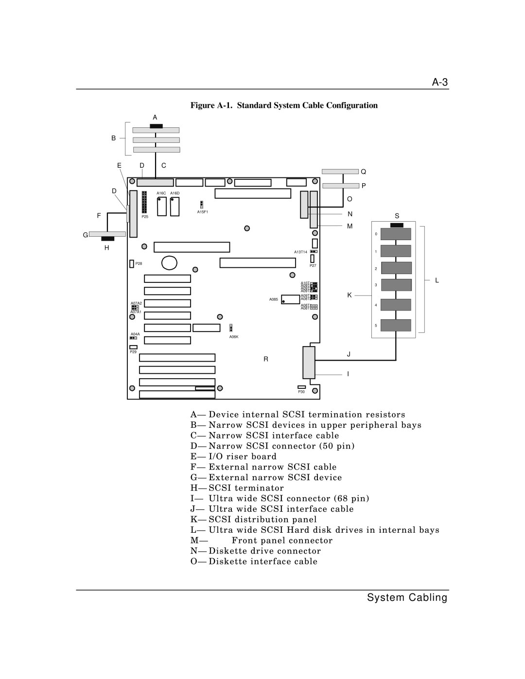
Figure A-1. Standard System Cable Configuration
A
B
E
D
F
G |
H |
|
|
|
|
|
|
|
|
|
|
|
|
|
|
|
|
|
|
|
|
|
|
|
|
|
|
|
|
|
|
|
|
|
|
|
|
|
|
|
|
|
|
|
|
|
|
|
|
|
|
|
|
|
|
|
|
|
|
|
|
|
|
|
|
|
|
|
|
|
|
|
|
|
|
|
|
|
|
|
|
|
|
|
|
|
|
|
|
|
|
|
|
|
|
|
|
|
|
|
|
|
|
|
| D | C | |||||||||||||
|
|
|
|
|
|
|
|
|
|
|
|
|
|
|
|
|
|
|
|
|
|
|
|
|
|
|
|
|
|
|
|
|
|
A16C | A16D |
| A15F1 |
P25 |
|
![]() Q
Q
![]() P
P
O
N
M
S
0
![]()
![]() P28
P28
A07A2
A07A1
A04A
P29
A085
A06K
R
A13T14
P27
A10T |
A09T4 |
A09T3 |
A09T2 |
A09T1 |
A08T2 |
A08T1 |
A08T |
K
J
1
2
3
4
5
L
I
P30
A— Device internal SCSI termination resistors B— Narrow SCSI devices in upper peripheral bays C— Narrow SCSI interface cable
D— Narrow SCSI connector (50 pin) E— I/O riser board
F— External narrow SCSI cable G— External narrow SCSI device H— SCSI terminator
I— Ultra wide SCSI connector (68 pin) J— Ultra wide SCSI interface cable K— SCSI distribution panel
L— Ultra wide SCSI Hard disk drives in internal bays
M— Front panel connector N— Diskette drive connector O— Diskette interface cable
System Cabling