|
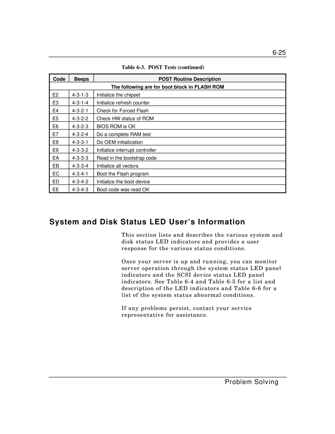
| Table |
|
|
|
Code | Beeps | POST Routine Description |
|
| The following are for boot block in FLASH ROM |
E2 | Initialize the chipset | |
E3 | Initialize refresh counter | |
E4 | Check for Forced Flash | |
E5 | Check HW status of ROM | |
E6 | BIOS ROM is OK | |
E7 | Do a complete RAM test | |
E8 | Do OEM initialization | |
E9 | Initialize interrupt controller | |
EA | Read in the bootstrap code | |
EB | Initialize all vectors | |
EC | Boot the Flash program | |
ED | Initialize the boot device | |
EE | Boot code was read OK |
System and Disk Status LED User’s Information
This section lists and describes the various system and disk status LED indicators and provides a user response for the various status conditions.
Once your server is up and running, you can monitor server operation through the system status LED panel indicators and the SCSI device status LED panel indicators. See Table
If any problems persist, contact your service representative for assistance.