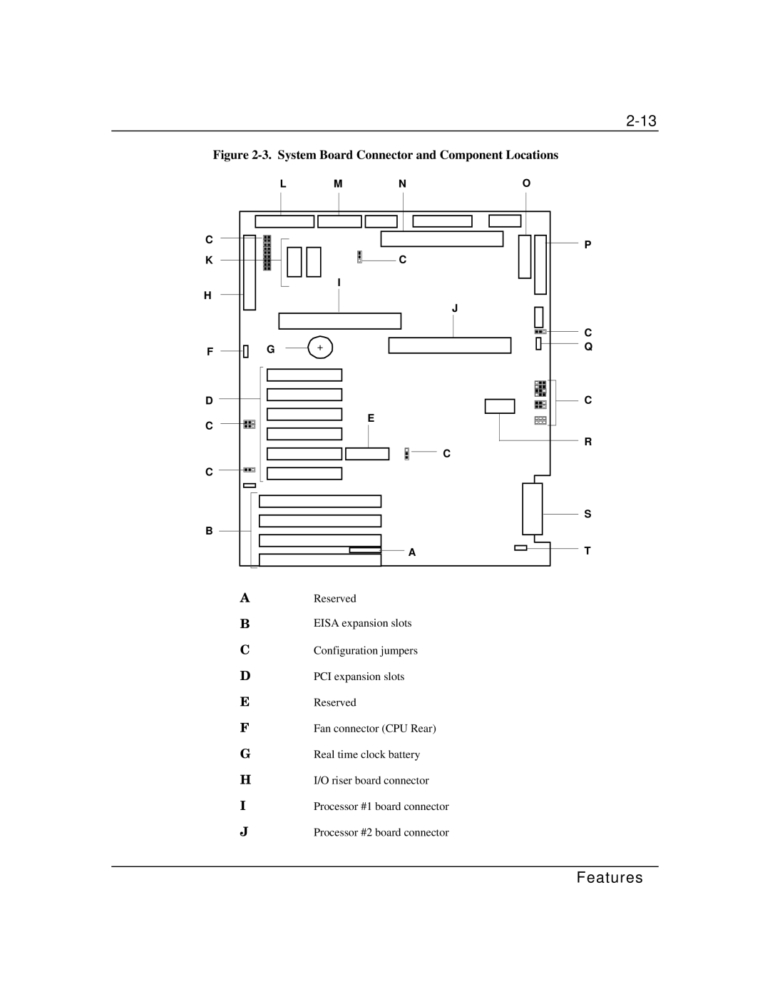
Figure 2-3. System Board Connector and Component Locations
LMNO
C |
|
K | C |
| I |
H |
|
| J |
F | G | + |
P
C Q
D
C
C
B
E
C
C
R
S
|
|
|
|
| A |
|
|
|
|
|
|
|
|
|
|
|
|
|
|
|
|
|
|
A | Reserved |
| |||||||||
B | EISA expansion slots |
| |||||||||
C | Configuration jumpers |
| |||||||||
D | PCI expansion slots |
| |||||||||
E | Reserved |
| |||||||||
F | Fan connector (CPU Rear) |
| |||||||||
G | Real time clock battery |
| |||||||||
H | I/O riser board connector |
| |||||||||
I | Processor #1 board connector |
| |||||||||
J | Processor #2 board connector |
| |||||||||
T