Table 2-5. Power LED Indicators
LED | Status | Description | Response |
|
|
|
|
Off | Power is off | None required - normal | |
| Green | Power is on | None required - normal |
|
|
|
|
Alarm | Off | No alarm | None required - normal |
| Amber | Power failure | Replace Power supply |
|
| Abnormal Power temperature | Clean air passages |
|
| Power FAN alarm | Replace Power supply |
|
| Replace Power supply | |
|
|
|
|
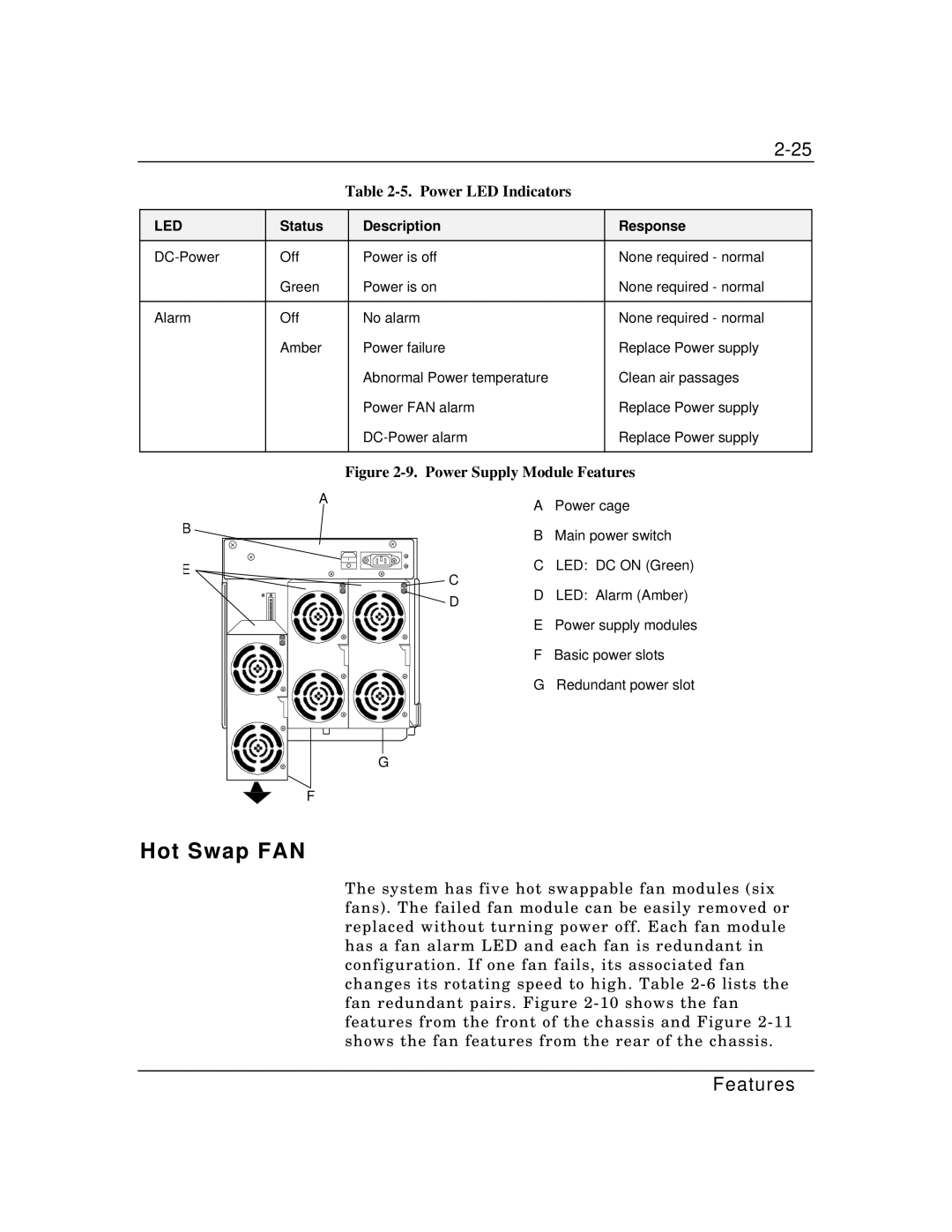
Figure 2-9. Power Supply Module Features
B
E
A |
| A | Power cage |
|
| ||
|
| B | Main power switch |
| C | C LED: DC ON (Green) | |
| D | LED: Alarm (Amber) | |
| D | ||
|
|
| |
|
| E | Power supply modules |
|
| F | Basic power slots |
|
| G | Redundant power slot |
G
F
Hot Swap FAN
The system has five hot swappable fan modules (six fans). The failed fan module can be easily removed or replaced without turning power off. Each fan module has a fan alarm LED and each fan is redundant in configuration. If one fan fails, its associated fan changes its rotating speed to high. Table