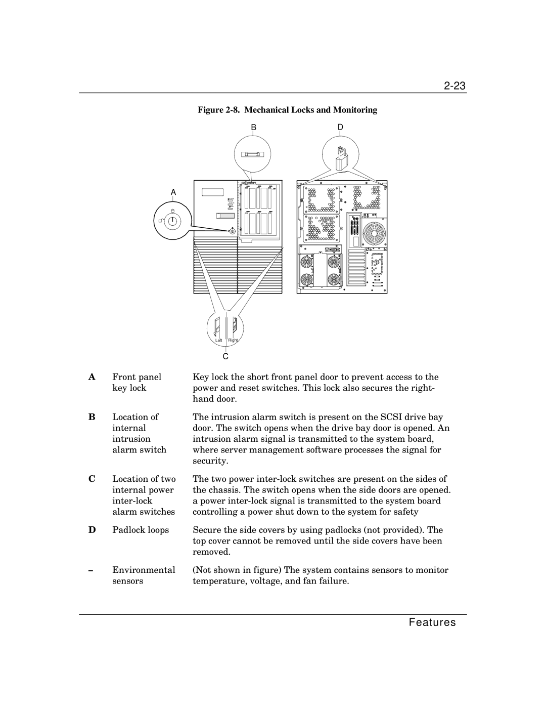
Figure 2-8. Mechanical Locks and Monitoring
BD
A
![]() POWER
POWER
STATUS
![]()
![]() DISK
DISK
|
|
|
|
|
|
|
|
|
|
|
|
|
|
|
|
|
|
|
| Left | Right | ||
|
|
|
|
|
|
|
| C | |||
A | Front panel | Key lock the short front panel door to prevent access to the | |||
| key lock | power and reset switches. This lock also secures the right- | |||
|
| hand door. | |||
B | Location of | The intrusion alarm switch is present on the SCSI drive bay | |||
| internal | door. The switch opens when the drive bay door is opened. An | |||
| intrusion | intrusion alarm signal is transmitted to the system board, | |||
| alarm switch | where server management software processes the signal for | |||
|
| security. | |||
C | Location of two | The two power | |||
| internal power | the chassis. The switch opens when the side doors are opened. | |||
| a power | ||||
| alarm switches | controlling a power shut down to the system for safety | |||
D | Padlock loops | Secure the side covers by using padlocks (not provided). The | |||
|
| top cover cannot be removed until the side covers have been | |||
|
| removed. | |||
– | Environmental | (Not shown in figure) The system contains sensors to monitor | |||
| sensors | temperature, voltage, and fan failure. | |||