|
| ||
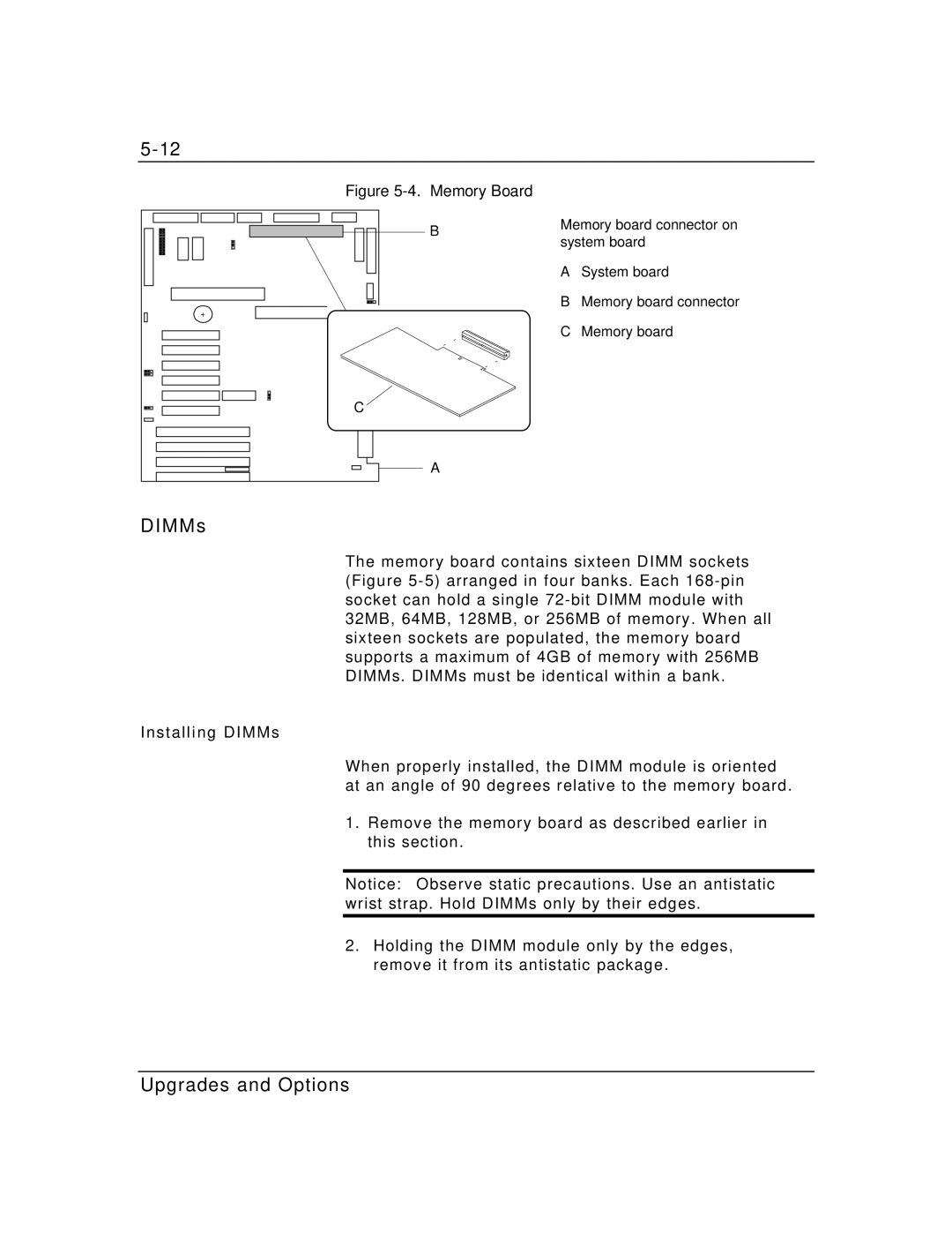
Figure |
|
| |
B | Memory board connector on | ||
system board | |||
| |||
| A | System board | |
+ | B | Memory board connector | |
|
| ||
| C | Memory board | |
C |
|
| |
A |
|
| |
DIM M s |
|
| |
The memory board contains sixteen DIMM sockets (Figure
Installing DIMMs
When properly installed, the DIMM module is oriented at an angle of 90 degrees relative to the memory board.
1.Remove the memory board as described earlier in this section.
Notice: Observe static precautions. Use an antistatic wrist strap. Hold DIMMs only by their edges.
2.Holding the DIMM module only by the edges, remove it from its antistatic package.