Automation and Drives - SCE
Binector Symbols
Connectors
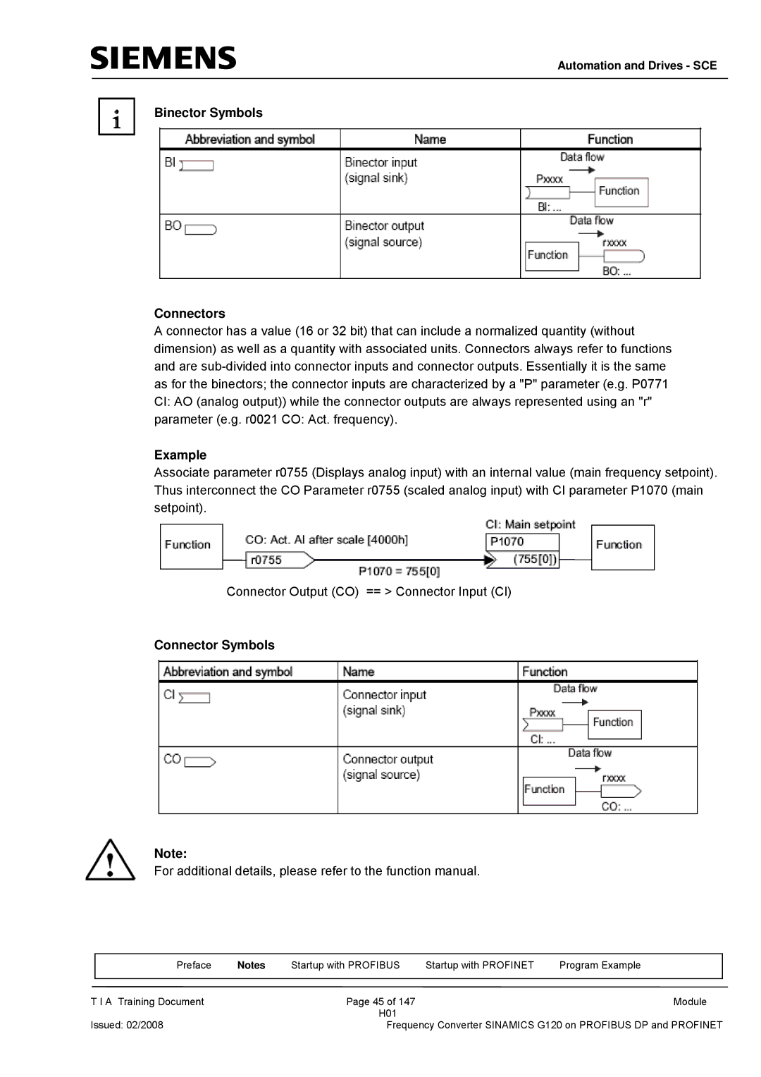
A connector has a value (16 or 32 bit) that can include a normalized quantity (without dimension) as well as a quantity with associated units. Connectors always refer to functions and are
Example
Associate parameter r0755 (Displays analog input) with an internal value (main frequency setpoint). Thus interconnect the CO Parameter r0755 (scaled analog input) with CI parameter P1070 (main setpoint).
Connector Output (CO) == > Connector Input (CI)
Connector Symbols
Note:
For additional details, please refer to the function manual.
| Preface | Notes | Startup with PROFIBUS | Startup with PROFINET | Program Example |
|
|
|
|
|
|
T I A Training Document |
| Page 45 of 147 |
| Module | |
|
|
| H01 |
|
|
Issued: 02/2008 |
| Frequency Converter SINAMICS G120 on PROFIBUS DP and PROFINET | |||
