Automation and Drives - SCE
3.4.3Setting the Frequency Setpoints with DIP Switches
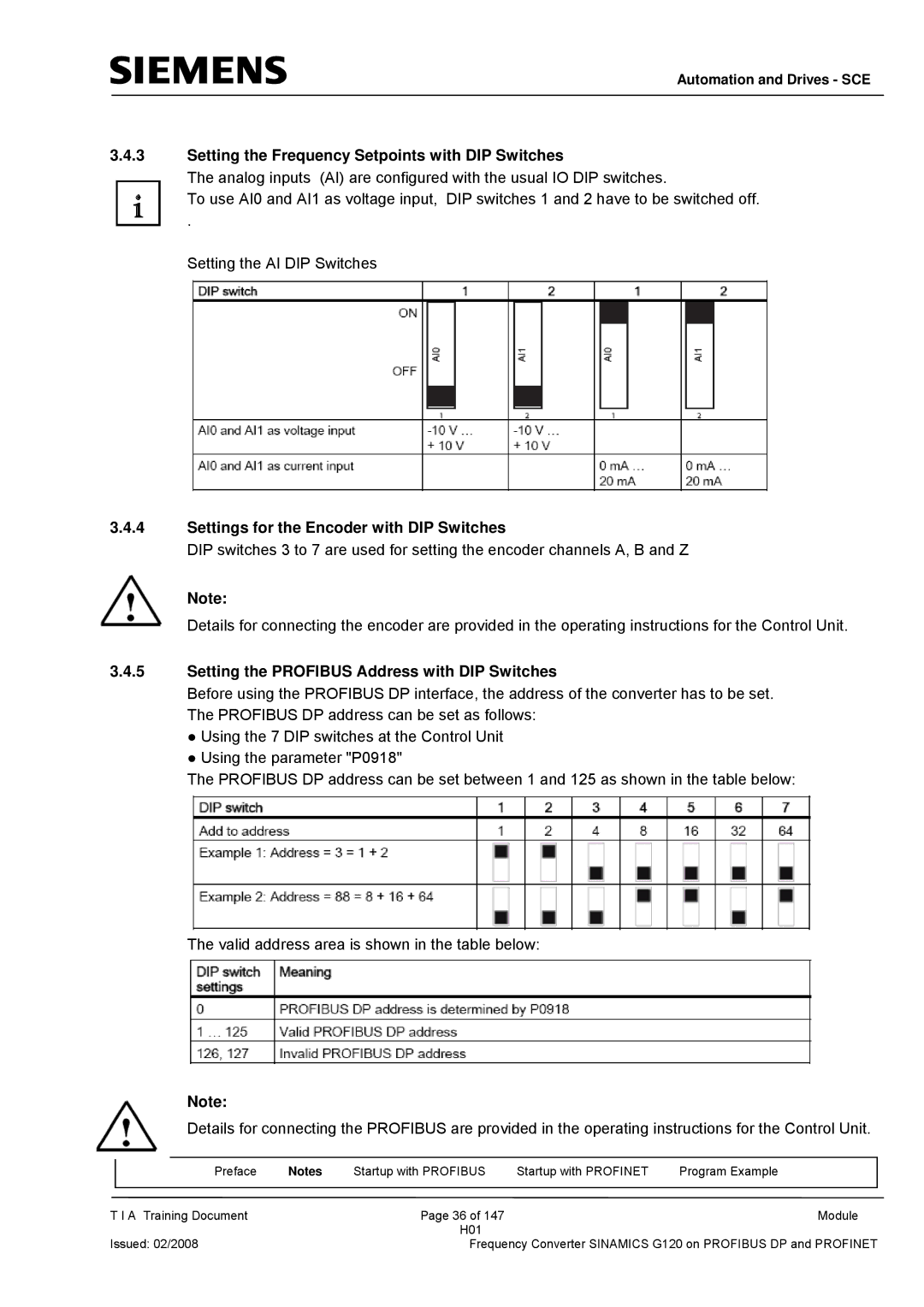
The analog inputs (AI) are configured with the usual IO DIP switches.
To use AI0 and AI1 as voltage input, DIP switches 1 and 2 have to be switched off.
.
Setting the AI DIP Switches
3.4.4Settings for the Encoder with DIP Switches
DIP switches 3 to 7 are used for setting the encoder channels A, B and Z
Note:
Details for connecting the encoder are provided in the operating instructions for the Control Unit.
3.4.5Setting the PROFIBUS Address with DIP Switches
Before using the PROFIBUS DP interface, the address of the converter has to be set. The PROFIBUS DP address can be set as follows:
●Using the 7 DIP switches at the Control Unit
●Using the parameter "P0918"
The PROFIBUS DP address can be set between 1 and 125 as shown in the table below:
The valid address area is shown in the table below:
Note:
Details for connecting the PROFIBUS are provided in the operating instructions for the Control Unit.
|
| Preface | Notes | Startup with PROFIBUS | Startup with PROFINET | Program Example |
|
|
|
|
|
|
|
T I A Training Document |
| Page 36 of 147 |
| Module | ||
|
|
|
| H01 |
|
|
Issued: 02/2008 |
| Frequency Converter SINAMICS G120 on PROFIBUS DP and PROFINET | ||||