Automation and Drives - SCE
Note:
A complete parameter list with a detailed description of all parameters, as well as overview diagrams of the internal program structure (function charts) are provided in the List Manual.
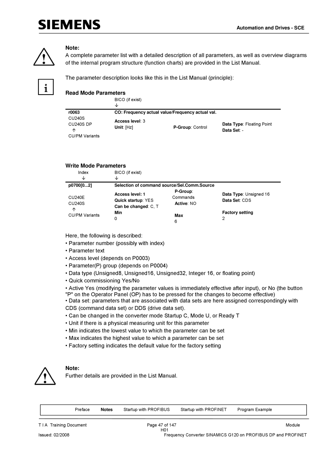
The parameter description looks like this in the List Manual (principle):
Read Mode Parameters
BICO (if exist)
È
r0063 | CO: Frequency actual value/Frequency actual val. |
| ||
CU240S | Access level: 3 |
|
| |
CU240S DP |
| Data Type: Floating Point | ||
Unit: [Hz] | ||||
Ç | Data Set: - | |||
|
| |||
CU/PM Variants
Write Mode Parameters
Index | BICO (if exist) |
|
| |
È | È |
|
| |
|
|
| ||
p0700[0...2] | Selection of command source/Sel.Comm.Source |
| ||
| Access level: 1 | Data Type: Unsigned 16 | ||
CU240E | Commands | |||
Quick startup: YES | Data Set: CDS | |||
CU240S | Active: NO | |||
Can be changed: C, T |
| |||
Ç |
|
| ||
Min |
| Factory setting | ||
CU/PM Variants | Max | |||
0 | 2 | |||
| 6 | |||
|
|
| ||
Here, the following is described:
•Parameter number (possibly with index)
•Parameter text
•Access level (depends on P0003)
•Parameter(P) group (depends on P0004)
•Data type (Unsigned8, Unsigned16, Unsigned32, Integer 16, or floating point)
•Quick commissioning Yes/No
•Active Yes (modifying the parameter values is immediately effective after input), or No (the button "P" on the Operator Panel (OP) has to be pressed for the changes to become effective)
•Data set: parameters that are associated with data sets are here assigned correspondingly with CDS (command data set) or DDS (drive data set).
•Can be changed in the converter mode Startup C, Mode U, or Ready T
•Unit if there is a physical measuring unit for this parameter
•Min indicates the lowest value to which the parameter can be set
•Max indicates the highest value to which a parameter can be set
•Factory setting indicates the default value for the factory setting
Note:
Further details are provided in the List Manual.
| Preface | Notes | Startup with PROFIBUS | Startup with PROFINET | Program Example |
|
|
|
|
|
|
T I A Training Document |
| Page 47 of 147 |
| Module | |
|
|
| H01 |
|
|
Issued: 02/2008 |
| Frequency Converter SINAMICS G120 on PROFIBUS DP and PROFINET | |||