Chapter 7. PARAMETER SETUP
■Description of setup data settings
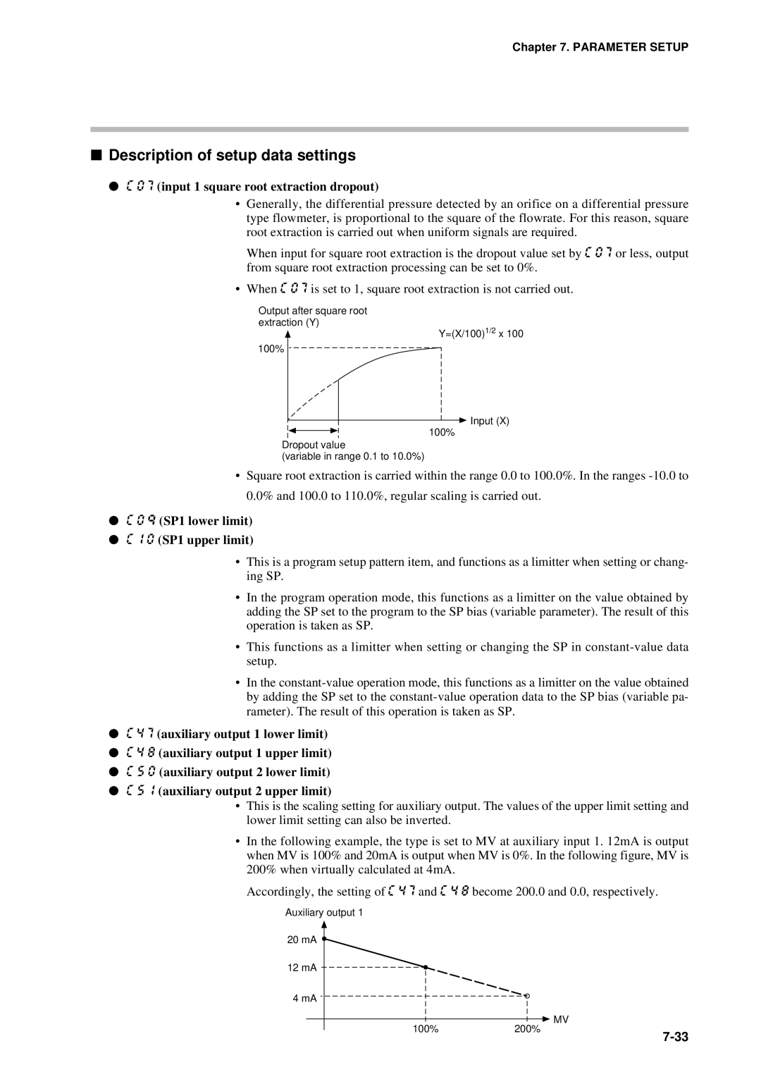
●C 0 7 (input 1 square root extraction dropout)
•Generally, the differential pressure detected by an orifice on a differential pressure type flowmeter, is proportional to the square of the flowrate. For this reason, square root extraction is carried out when uniform signals are required.
When input for square root extraction is the dropout value set by C 0 7 or less, output from square root extraction processing can be set to 0%.
•When C 0 7 is set to 1, square root extraction is not carried out.
Output after square root
extraction (Y)
Y=(X/100)1/2 x 100
100%
![]() Input (X) 100%
Input (X) 100%
Dropout value
(variable in range 0.1 to 10.0%)
•Square root extraction is carried within the range 0.0 to 100.0%. In the ranges
●C 0 q (SP1 lower limit)
●C 1 0 (SP1 upper limit)
•This is a program setup pattern item, and functions as a limitter when setting or chang- ing SP.
•In the program operation mode, this functions as a limitter on the value obtained by adding the SP set to the program to the SP bias (variable parameter). The result of this operation is taken as SP.
•This functions as a limitter when setting or changing the SP in
•In the
●C 4 7 (auxiliary output 1 lower limit)
●C 4 8 (auxiliary output 1 upper limit)
●C 5 0 (auxiliary output 2 lower limit)
●C 5 1 (auxiliary output 2 upper limit)
•This is the scaling setting for auxiliary output. The values of the upper limit setting and lower limit setting can also be inverted.
•In the following example, the type is set to MV at auxiliary input 1. 12mA is output when MV is 100% and 20mA is output when MV is 0%. In the following figure, MV is 200% when virtually calculated at 4mA.
Accordingly, the setting of C 4 7 and C 4 8 become 200.0 and 0.0, respectively.
Auxiliary output 1 |
|
20 mA |
|
12 mA |
|
4 mA |
|
100% | MV |
200% | |
|