Chapter 7. PARAMETER SETUP
●C 6 5 (time display)
0:Remaining segment time
1:Total operation time
•This selects the time display in the basic display state in the program operation mode.
•When set to 0, in the READY mode, the time setting value of the currently selected segment is displayed.
•When set to 0, in the RUN, HOLD, FAST or END modes, the remaining time for the currently executing segment is displayed after being rounded down.
For example, if the remaining time is 1h, 30min, 59s when the time unit is set to “h:min”, the time display is “1 .3 0”.
•When set to 1, in the READY mode, the time display is “0 .0 0”.
•When set to 1, in the RUN, HOLD, FAST or END modes, the time it takes to shift from the READY to the RUN mode is displayed after being round down. Also, after “q q .5 q” the time display changes to “0 .0 0”.
For example, if the remaining time is 101h, 30min, 59s when the total operation time is set to “h:min”, the time display is “1 .3 0”.
•In the FAST mode, the time display changes according to the FAST scale if this pa- rameter is set to either 0 or 1.
●C 6 6 (PV display)
This selects PV display in the basic display state. You can select between numerical display or no display at all. The setting of this parameter does not influence
Also, to eliminate PV alarm display or PV alarm event output, select the thermocouple range by the input range to
●C 7 2 (cold junction compensation)
0:Compensated internally
1:Compensated externally
•This selects how thermocouple cold junctions are to be compensated.
•When set to 1, carry out 0° C compensation by an ice box, for example.
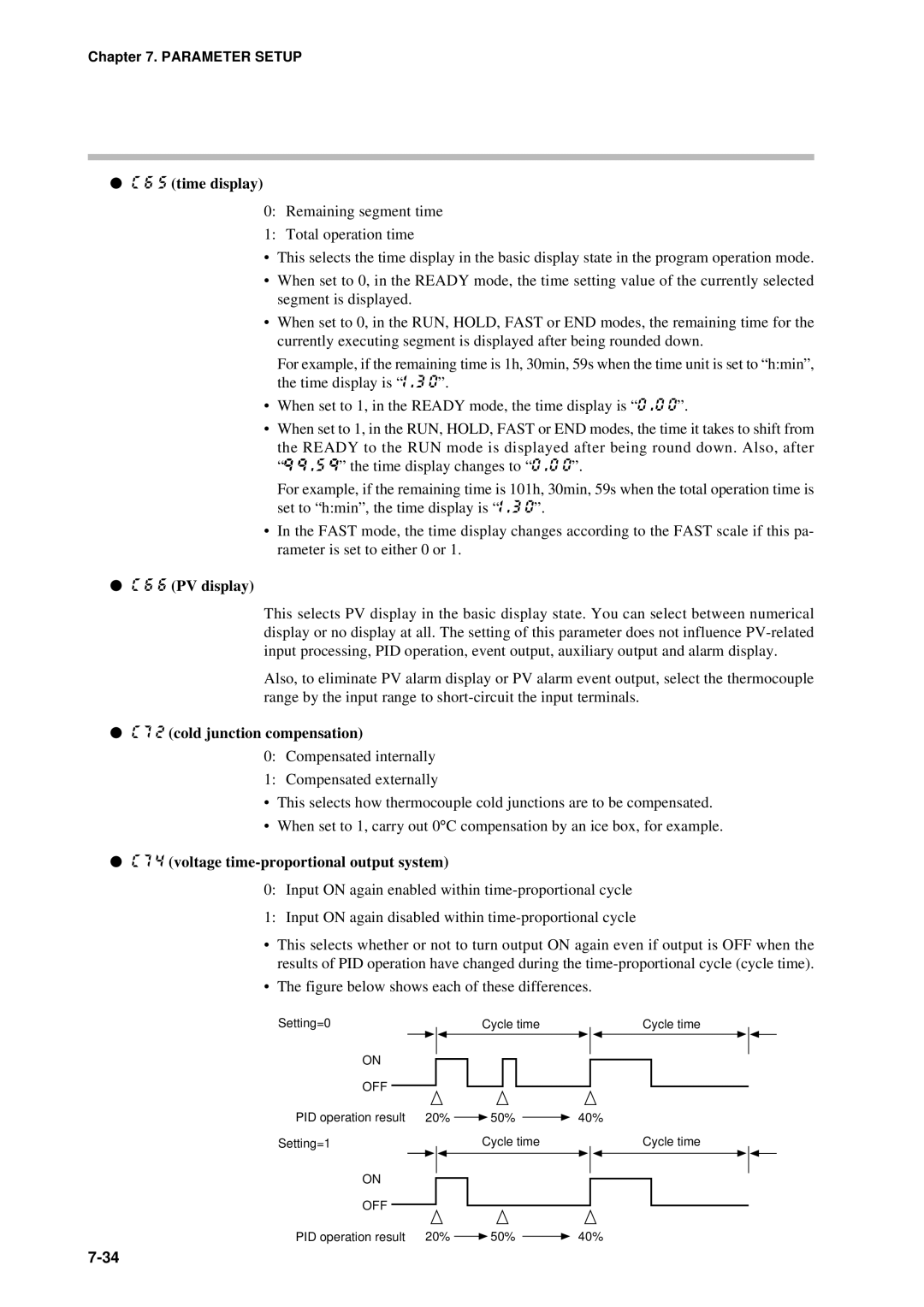
●C 7 4 (voltage time-proportional output system)
0:Input ON again enabled within
1:Input ON again disabled within
•This selects whether or not to turn output ON again even if output is OFF when the results of PID operation have changed during the
•The figure below shows each of these differences.
Setting=0 |
|
|
|
|
|
| Cycle time |
|
|
| Cycle time |
| |||||
|
|
|
|
|
|
|
|
|
| ||||||||
ON |
|
|
|
|
|
|
|
|
|
|
|
|
|
|
|
| |
|
|
|
|
|
|
|
|
|
|
|
|
|
|
|
| ||
|
|
|
|
|
|
|
|
|
|
|
|
|
|
|
| ||
OFF |
|
|
|
|
|
|
|
|
|
|
|
|
|
|
|
|
|
|
|
|
|
|
|
|
|
|
|
|
|
|
|
|
|
| |
PID operation result | 20% |
|
| 50% |
|
| 40% |
|
| ||||||||
|
|
|
| ||||||||||||||
Setting=1 |
|
|
|
|
|
| Cycle time |
|
|
| Cycle time |
| |||||
ON |
|
|
|
|
|
|
|
|
|
|
|
|
|
|
|
| |
|
|
|
|
|
|
|
|
|
|
|
|
|
|
|
| ||
|
|
|
|
|
|
|
|
|
|
|
|
|
|
|
| ||
OFF |
|
|
|
|
|
|
|
|
|
|
|
|
|
|
|
|
|
| 20% |
|
| 50% |
|
| 40% |
|
| ||||||||
PID operation result |
|
|
|
|
| ||||||||||||
|
|
|
|
| |||||||||||||
