Chapter 6. OPERATION
•Auto-tuning in all instances involves calculating the downtime and critical sensitivity of the line according to two limit cycles and PID values according to suitable charac- teristic equations for each, and automatically writing these PID values.
•During execution of auto-tuning, PV fluctuates according to fluctuations in MV. Be- fore executing auto-tuning, make sure that fluctuations in PV will not cause controller trouble.
•Normally, suitable values are written by setting variable parameter At setting to 1 or 3. However, when executing auto-tuning on a line that easily overshoots, either set to 2, or also use smart-tuning for carrying out overshoot inhibit control. Setting to 3 ex- ecutes AT by neural net so that the suitable value is calculated for wider range applica- tions.
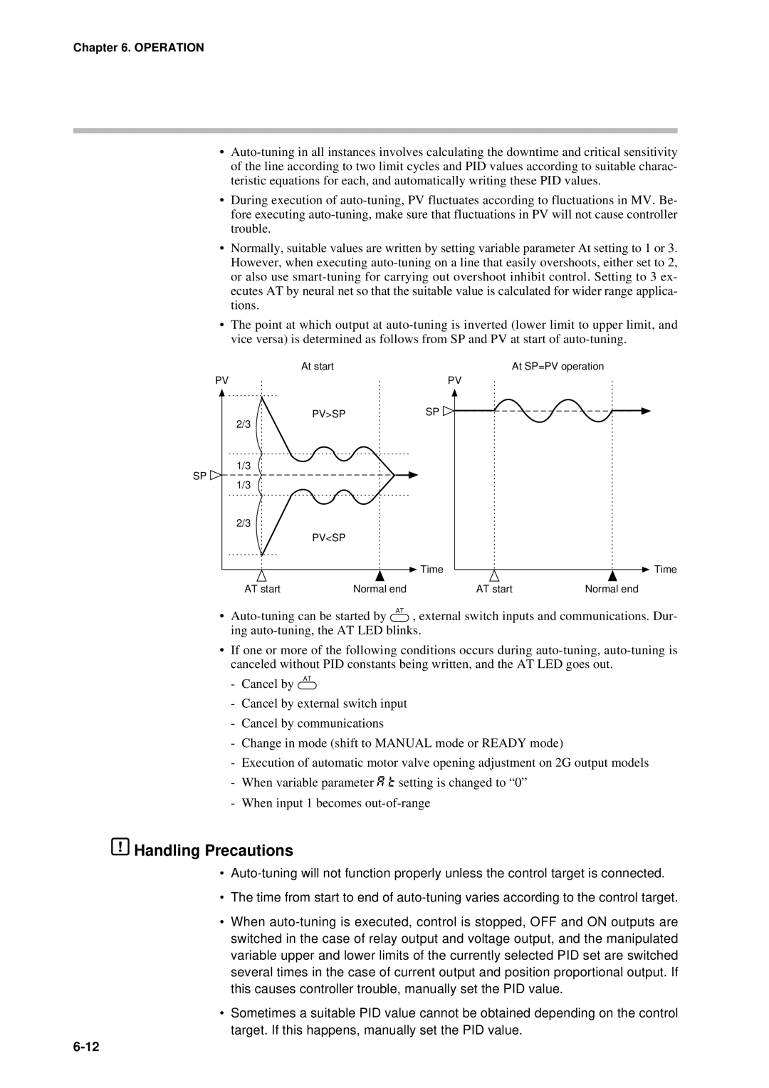
•The point at which output at auto-tuning is inverted (lower limit to upper limit, and vice versa) is determined as follows from SP and PV at start of auto-tuning.
At start | At SP=PV operation |
PV | PV |
PV>SP | SP |
2/3 | |
1/3
SP
1/3
2/3
| PV<SP | | |
| | Time | Time |
AT start | Normal end | AT start | Normal end |
•Auto-tuning can be started by AT , external switch inputs and communications. Dur- ing auto-tuning, the AT LED blinks.
•If one or more of the following conditions occurs during auto-tuning, auto-tuning is canceled without PID constants being written, and the AT LED goes out.
-Cancel by AT
-Cancel by external switch input
-Cancel by communications
-Change in mode (shift to MANUAL mode or READY mode)
-Execution of automatic motor valve opening adjustment on 2G output models
-When variable parameter A t setting is changed to “0”
-When input 1 becomes out-of-range
 Handling Precautions
•Auto-tuning will not function properly unless the control target is connected.
•The time from start to end of auto-tuning varies according to the control target.
•When auto-tuning is executed, control is stopped, OFF and ON outputs are switched in the case of relay output and voltage output, and the manipulated variable upper and lower limits of the currently selected PID set are switched several times in the case of current output and position proportional output. If this causes controller trouble, manually set the PID value.
•Sometimes a suitable PID value cannot be obtained depending on the control target. If this happens, manually set the PID value.
6-12