Chapter 8. PROGRAM SETUP
■Display details
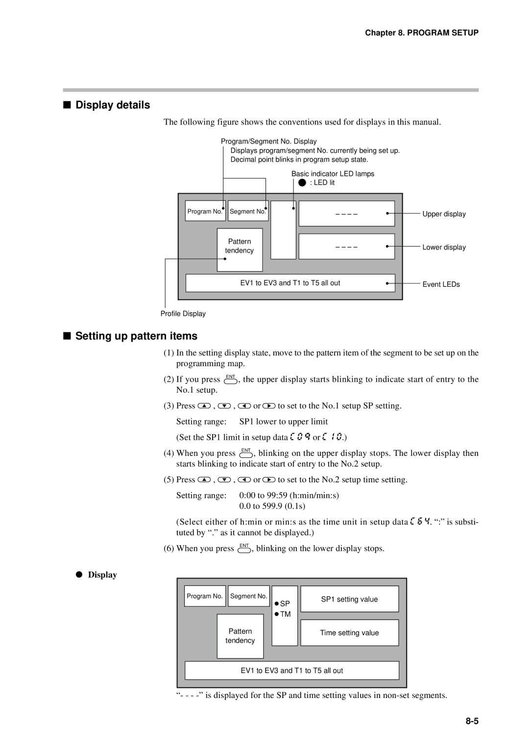
The following figure shows the conventions used for displays in this manual.
Program/Segment No. Display
Displays program/segment No. currently being set up.
Decimal point blinks in program setup state.
Basic indicator LED lamps : LED lit
Program No. Segment No.
Pattern
tendency
SP TM
– – – – |
|
| Upper display |
|
| ||
|
|
|
|
|
|
|
|
– – – – |
|
| Lower display |
|
| ||
|
|
|
|
EV1 to EV3 and T1 to T5 all out |
|
| Event LEDs |
|
| ||
|
|
|
|
Profile Display
■Setting up pattern items
(1)In the setting display state, move to the pattern item of the segment to be set up on the programming map.
(2)If you press ENT , the upper display starts blinking to indicate start of entry to the No.1 setup.
(3)Press ![]() ,
, ![]() ,
, ![]() or
or ![]() to set to the No.1 setup SP setting. Setting range: SP1 lower to upper limit
to set to the No.1 setup SP setting. Setting range: SP1 lower to upper limit
(Set the SP1 limit in setup data C 0 Q or C 1 0.)
(4)When you press ENT , blinking on the upper display stops. The lower display then starts blinking to indicate start of entry to the No.2 setup.
(5)Press ![]() ,
, ![]() ,
, ![]() or
or ![]() to set to the No.2 setup time setting. Setting range: 0:00 to 99:59 (h:min/min:s)
to set to the No.2 setup time setting. Setting range: 0:00 to 99:59 (h:min/min:s)
0.0to 599.9 (0.1s)
(Select either of h:min or min:s as the time unit in setup data C 6 4. “:” is substi- tuted by “.” as it cannot be displayed.)
(6) When you press ENT , blinking on the lower display stops.
●Display
Program No. Segment No.
Pattern
tendency
![]() SP
SP
![]() TM
TM
SP1 setting value
Time setting value
EV1 to EV3 and T1 to T5 all out
“- - -