Chapter 10. SPECIFICATIONS
Chapter 10. SPECIFICATIONS
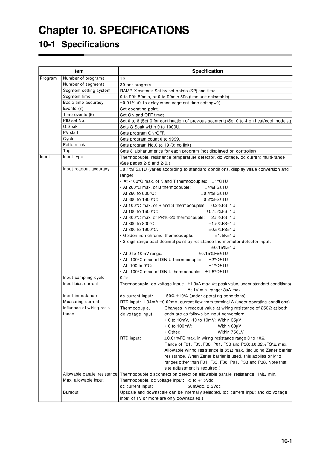
10-1 Specifications
| Item |
| Specification |
|
| |||
Program | Number of programs | 19 |
|
|
|
|
|
|
| Number of segments | 30 per program |
|
|
|
|
|
|
| Segment setting system |
|
|
| ||||
| Segment time | 0 to 99h 59min, or 0 to 99min 59s (time unit selectable) |
|
| ||||
| Basic time accuracy | ± 0.01% (0.1s delay when segment time setting=0) |
|
|
| |||
| Events (3) | Set operating point. |
|
|
|
|
|
|
| Time events (5) | Set ON and OFF times. |
|
|
|
|
| |
| PID set No. | Set 0 to 8 (Set 0 for continuation of previous segment) (Set 0 to 4 on heat/cool models.) | ||||||
| G.Soak | Sets G.Soak width 0 to 1000U. |
|
|
|
|
| |
| PV start | Sets program ON/OFF. |
|
|
|
|
| |
| Cycle | Sets program count 0 to 9999. |
|
|
|
|
| |
| Pattern link | Sets program No.0 to 19 (0: no link) |
|
|
|
|
| |
| Tag | Sets 8 alphanumerics for each program (not displayed on controller) | ||||||
Input | Input type | Thermocouple, resistance temperature detector, dc voltage, dc current | ||||||
|
| (See pages |
|
|
|
|
| |
|
|
| ||||||
| Input readout accuracy | ± 0.1%FS± 1U (varies according to standard conditions, display value conversion and | ||||||
|
| range) |
|
|
|
|
|
|
|
| • At | ± 1° C1U |
|
| |||
|
| • At 260° C max. of B thermocouple: | ± | 4%FS± | 1U |
|
| |
|
| At 260 to 800° C: |
| ± 0.4%FS± | 1U |
|
| |
|
| At 800 to 1800° C: |
| ± 0.2%FS± | 1U |
|
| |
|
| • At 100° C max. of R and S thermocouples: ± 0.2%FS± | 1U |
| ||||
|
| At 100 to 1600° C: |
| ± 0.15%FS± | 1U |
| ||
|
| • At 300° C max. of | ± 2.5%FS± | 1U |
| |||
|
| At 300 to 800° C: |
|
| ± 1.5%FS± | 1U |
| |
|
| At 800 to 1900° C: |
|
| ± 0.5%FS± | 1U |
| |
|
| • Golden iron chromel thermocouple: |
| ± 1.5K± | 1U |
| ||
|
| • | ||||||
|
|
|
|
| ± 0.15%± | 1U |
| |
|
| • At 0 to 10mV range: | ± | 0.15%FS± | 1U |
|
| |
|
| • At |
| ± 2° C± | 1U |
|
| |
|
| At |
|
| ± 1° C± | 1U |
|
|
|
| • At | ± | 1.5° C± | 1U |
|
| |
| Input sampling cycle | 0.1s |
|
|
|
|
|
|
| Input bias current | Thermocouple, dc voltage input: ± 1.3∝ A max. (at peak value, under standard conditions) | ||||||
|
|
| At 1V min. range: 3∝ A max. | |||||
| Input impedance | dc current input: | 50Ω ± 10% (under operating conditions) | |||||
| Measuring current | RTD input: 1.04mA ± 0.02mA, current flow from terminal A (under operating conditions) | ||||||
|
|
|
| |||||
| Influence of wiring resis- | Thermocouple, | Changes in readout value at wiring resistance of 250Ω at both | |||||
| tance | dc voltage input: | ends are as follows by input conversion: | |||||
|
|
| • 0 to 10mV, | V | ||||
|
|
| • 0 to 100mV: |
| Within 60∝ | V | ||
|
|
| • Other: |
| Within 750∝ V | |||
|
| RTD input: | ± 0.01%FS max. in wiring resistance range 0 to 10Ω | |||||
|
|
| Range of F01, F33, F38, P01, P33 and P38: ± 0.02%FS/Ω max. | |||||
|
|
| Allowable wiring resistance is 85Ω max. (including Zener barrier | |||||
|
|
| resistance. When Zener barrier is used, this applies only to | |||||
|
|
| ranges other than F01, F33, F38, P01, P33 and P38. Note that | |||||
|
|
| site adjustment is required.) |
|
|
| ||
|
|
| ||||||
| Allowable parallel resistance | Thermocouple disconnection detection allowable parallel resistance: 1MΩ min. | ||||||
| Max. allowable input | Thermocouple, dc voltage input: |
|
|
| |||
|
| dc current input: | 50mAdc, 2.5Vdc |
|
|
| ||
| Burnout | Upscale and downscale can be internally selected. (dc current input and dc voltage | ||||||
input of 1V or more are only downscaled.)