DCP301 Digital Program Controller User’s Manual
EN1I-6197 Issue 7 02/04
Warranty
Safety Precautions
Page
Handling Precautions
Name Model No ’ty Remarks
Unpacking
Parameter Setup
Wiring
Program Setup
Troubleshooting
Contents
Operation
Functions
Program Setup
Parameter Setup
Troubleshooting
Specifications
Calibration
Index
Conventions Used in This Manual
High accuracy achieved by multi-range input
Features
Wide range of control output types
Enhanced compatibility with PLC
Basic Function Blocks
RUN/HOLD Reset ADV Fast AUTO/MANUAL
Parameters
Data Structure
System configuration by CPL communications
System Configuration
Model selection guide
Model Numbers
Names & Functions of Parts
Structure
Console
Basic display state
Display
MAN
Category Function Key operation
Keys
Setup
Program setup
Assignment item
To start program copy
Loader jack
Functions using two or more keys
Input Type and Range No
Resistance temperature detector RTD
Inputs
Thermocouple
Input Format Range No Code Range programmable
Dc current, dc voltage
Mounting
External Dimensions
Panel Cutout Dimensions
Mounting locations
Mounting
Noise generating sources and countermeasures
Dust-proof cover
Type Confirmation on Display Operation Hard
Mounting method
Handling Precautions
Wiring Precautions
Wiring
Handling Precautions
Wiring
Compensating Lead
Hitachi Cable Co
Terminal Connections
Layout of Terminals and Recommended Lead Draw-out Direction
Connecting the Ground and Power Supply
Power supply
Ground
Wiring of Standard and Add-on Terminal Base
Standard terminal layout
Add-on terminal layout
Connecting input
Connecting Inputs analog inputs
Relay output 0D
Connecting control outputs outputs 1
Current output 5G
Position-proportional output 2G
Voltage output 6D
Heat/cool output 3D
Heat/cool output 5K
Connecting auxiliary outputs outputs 2
0D, 5G, 6D auxiliary outputs
2G, 3D, 5K auxiliary outputs
Connecting Event Output relay output
Connecting Time Event Output open-collector
Connecting External Switch RSW Input
Wiring
RS-485 interface
Connecting for Communications
Wire system RS-485 mutual connection
RDA RDB
Isolating Inputs and Outputs
Control outputs 0D, 5G, 6D, 3D, 5K
Control output 2G
Data
Data types
Functions
Patterns
Program Patterns
PV type events
Events 1 to
OFF H
Time events
Controller status events
Onoff
Time events 1 to
Segment No. events
PID set selection
Soak guarantee soak
Cycle
PV start
Pattern link
Modes
Mode types
Program operation
Constant-value operation
RUN
Mode transition
During program operation
During constant-value operation
Program end
Mode transition operations
Manual
Mode transition limitations
Controller and Programmer
Controller
Programmer
Input processing is carried out in the order shown below
Input Processing Functions
Output Processing Functions
Control output
5G output
0D, 6D output
2G output
Dv-L/HY-L Dv-H/HY-H
3D, 5K outputs
SP output
Auxiliary output
Auxiliary output
Startup flow
Turning the Power on
Switching the Basic Display
Disp functions
Display in program operation mode
Display
Output Model No Display
CYC
Display in constant-value operation mode
Motor valve opening % Output state of events 1 to
Program Selection
How to select the program No
External switch RSW inputs
External Switch RSW Operations
External switch input types
External Function Detection Method Switch No
Program selection
External Weighting State Switch No
Read timing
Timing of RSW1 to
Timing of RSW8 to 12, RUN and PV start
Auto-tuning AT
Manual Operation and Auto-tuning
Manual operation
Controller functions
Pvsp
Selecting the setting group in the parameter setup
Parameter Setup
D E is
Name Upper Remarks Display
Moving individual items in the parameter setup
9 C 0
How to register functions to keys
How to Use Para
How to register assignment items
Base Setting Group
Example
Item Code Setting Auxiliary Value Remarks Display
Operations by Para
Order Item to Call by
Basic Display Para key State Max items
Variable parameter settings P a R a
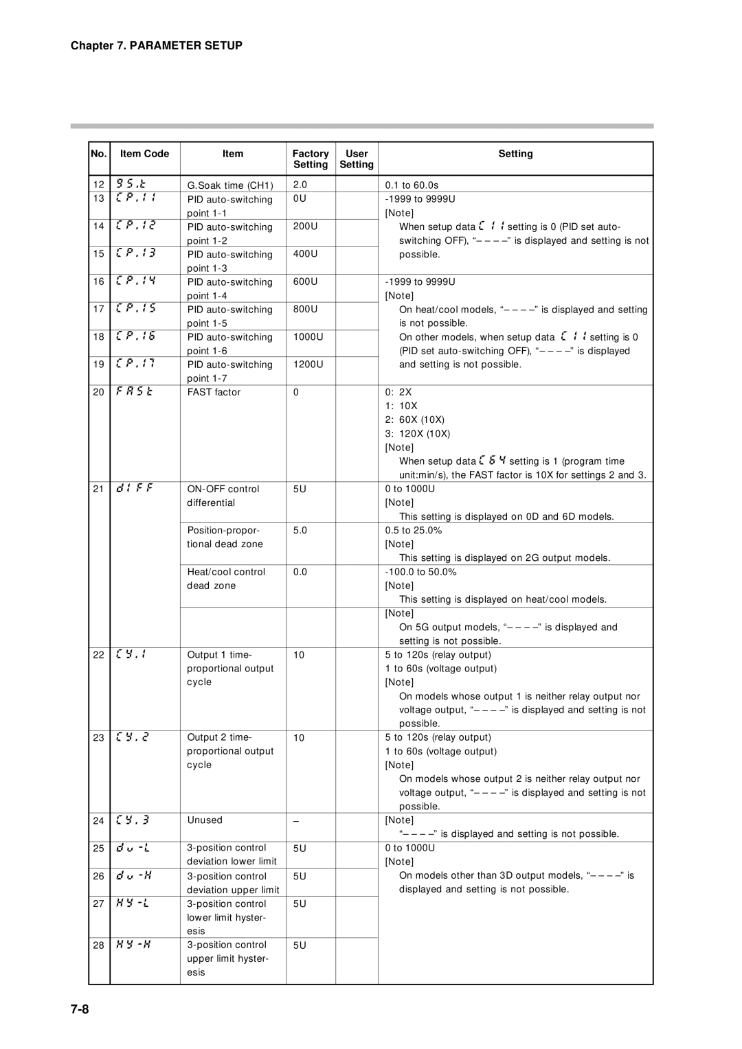
Parameter Setup List
S T
Parameter Setup
Description of variable parameter settings
C key lock
T C program protect
L MV change limit
U t PID operation initial MV
I D PID operation initialization
I D 2 degrees of freedom
Smart-tuning method selection
F F
Cool
State Heat-side Output Cool-side Output
Cmotor control method selection
Tmotor valve opening adjustment fully open/closed time
T motor valve opening automatic adjustment
Manual
Event configuration data settings E
Parameter Setup
Parameter Setup
Parameter Setup
1 event 1 standby 2 event 2 standby 3 event 3 standby
Description of event configuration data
PID Set
PID parameter settings P I d
Parameter Setup
Parameter Setup
Parameter Setup
Setup data settings S E t
Parameters C P 1 to C P
NOP
Ready
To input
ROM ID
Description of setup data settings
7 input 1 square root extraction dropout
SP1 lower limit 0 SP1 upper limit
6 PV display
5 time display
2 cold junction compensation
4 voltage time-proportional output system
8 voltage output 1 adjustment Voltage output 2 adjustment
Formulas 3 and 4 formulas must be satisfied
0 Special functions
1 Input 1 Zener barrier adjustment
3 CPL communications port selection
Table data settings T B L
To t -A . b To t -b . b
Description of table data settings
D E
Constant-value operation data settings C N S t
Program Setup
How to enter program setup
Selecting the program No. to set up
Basic Display State Func + Prog keys
Description of mode transition states see
Segment No Program No.1 setting 12 to
Programming map
Shaded items Cannot be moved
Display details
Setting up pattern items
Setting up events 1 to 3 items
When event type is PV type event
Display PV type event
When event type is time event
When event type is controller status event
Display time event
Time event No Setting value
Setting up time events 1 to
PI D
Setting up PID set No. items
Setting up G.Soak time-out items
Setting up G.Soak guarantee soak items
Setting up cycle items
Setting up PV start items
Deleting programs
Setting up pattern link items
Inserting and deleting segments
Display inserting segment
Display deleting segment
Copying Programs
P Y
E S
General Reset
Self-diagnostics at power on
Self-diagnostics and Alarm Code Display
Self-diagnostics at each sampling cycle
Intermittent self-diagnostics during operation
Self-diagnostics only when certain functions are operating
Alarm code display
Alarm categories
Cause Remedy
Trouble during Key Entry
Controller is in the Ready mode Press
Troubleshooting
Items cannot be changed by pressing in program setup state
RUN. HOLD, FAST, END
Motor Adjustment is Impossible
Normal wiring for reverse motor rotation
Normal wiring for direct motor rotation
Alarm display caused by wrong wiring and causes
C L
Replacing the Battery
BAT LED blinking
Items to prepare
Replacement procedure Handling Precautions
Remove the battery connector from the RAM board
Gray holder
Specifications
Specifications
Specification
10-1
RSW
10-2
Auto
10-3
10-4
10-5
10-6
10-7
Accessories/option list
10-8
Hard dust-proof cover set sold separately
Soft dust-proof cover set sold separately
Terminal cover set sold separately
10-9
Precautions before calibration
Equipment needed
11-1
11-2
Model number DCP30 * * * * ES
Calibration
Calibration Items for Each Model
11-3
AdJS
11-4
Calibration Flowchart 1/2
11-5
Calibration Flowchart 2/2
11-6
Enter calibration mode
Prog Display
SEG Display
Key test
Function test
11-7
Upper Display
Digital input test
Display test
11-8
Terminal
Digital output test for control output
Digital output test for event
11-9
PV calibration
Key
11-10
Range Table of CH1 TC Group Type Code Range No. Gain No
11-11
Current output calibration
Cold junction sensor calibration
Press ENT key
11-12
11-13
11. Current Outputs
11-14
Programming Map
Safety Requirements
Index-1
Index
Index-2
Control output SP output
Index-3
Time event output open-collector connection
00-08 3rd Edition
99-04 EN1I-6197 1st Edition 00-06 2nd Edition
01-06 4th Edition
03-06 5th Edition
Honeywell Service Centers
Argentina
No. CP-UM-5093E