GM29 INTEGRATOR’S MANUAL
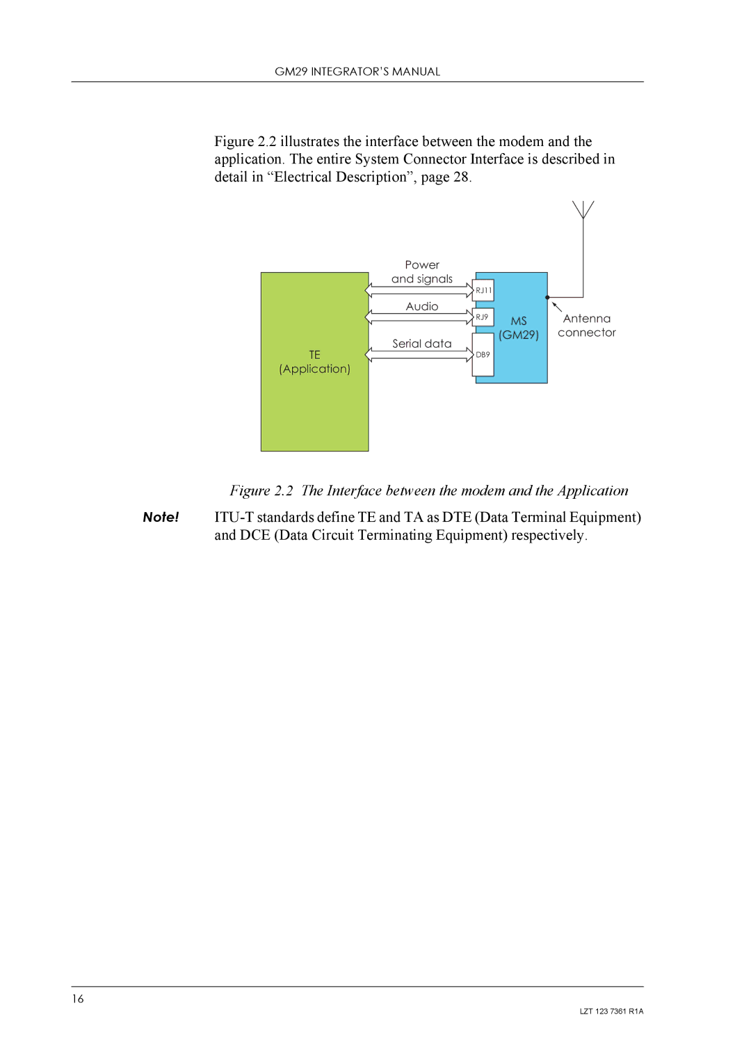
Figure 2.2 illustrates the interface between the modem and the application. The entire System Connector Interface is described in detail in “Electrical Description”, page 28.
TE
(Application)
Power
and signals
Audio
Serial data
RJ11
RJ9
DB9
MS Antenna (GM29) connector
Figure 2.2 The Interface between the modem and the Application
Note!
16
LZT 123 7361 R1A