2. ELECTRICAL DESCRIPTION
The power connector electrical characteristics are listed below:
Pin | Signal | Dir | Limits | Description |
|
|
|
|
|
1 | VCC | I | 5 - 32V | Positive power input |
|
|
|
|
|
2 | - | - | - | No connection |
|
|
|
|
|
3 | HR_IN | I | Active high control line used to switch | |
|
|
|
| off or reset the modem |
|
|
|
| VIH > 5V, VIL < 2V |
|
|
|
| Power off: 1s < t < 2s |
|
|
|
| Hard reset: t > 3.5s |
4 | TO_IN | I | Active high control line used to switch | |
|
|
|
| on the modem |
|
|
|
| VIH > 5V, VIL < 2V |
|
|
|
| Power on: t > 0.2s |
|
|
|
|
|
5 | - | - | - | No connection |
|
|
|
|
|
6 | GND | I | - | Negative power (ground) input and |
|
|
|
| return path for TO_IN and HR_IN |
|
|
|
|
|
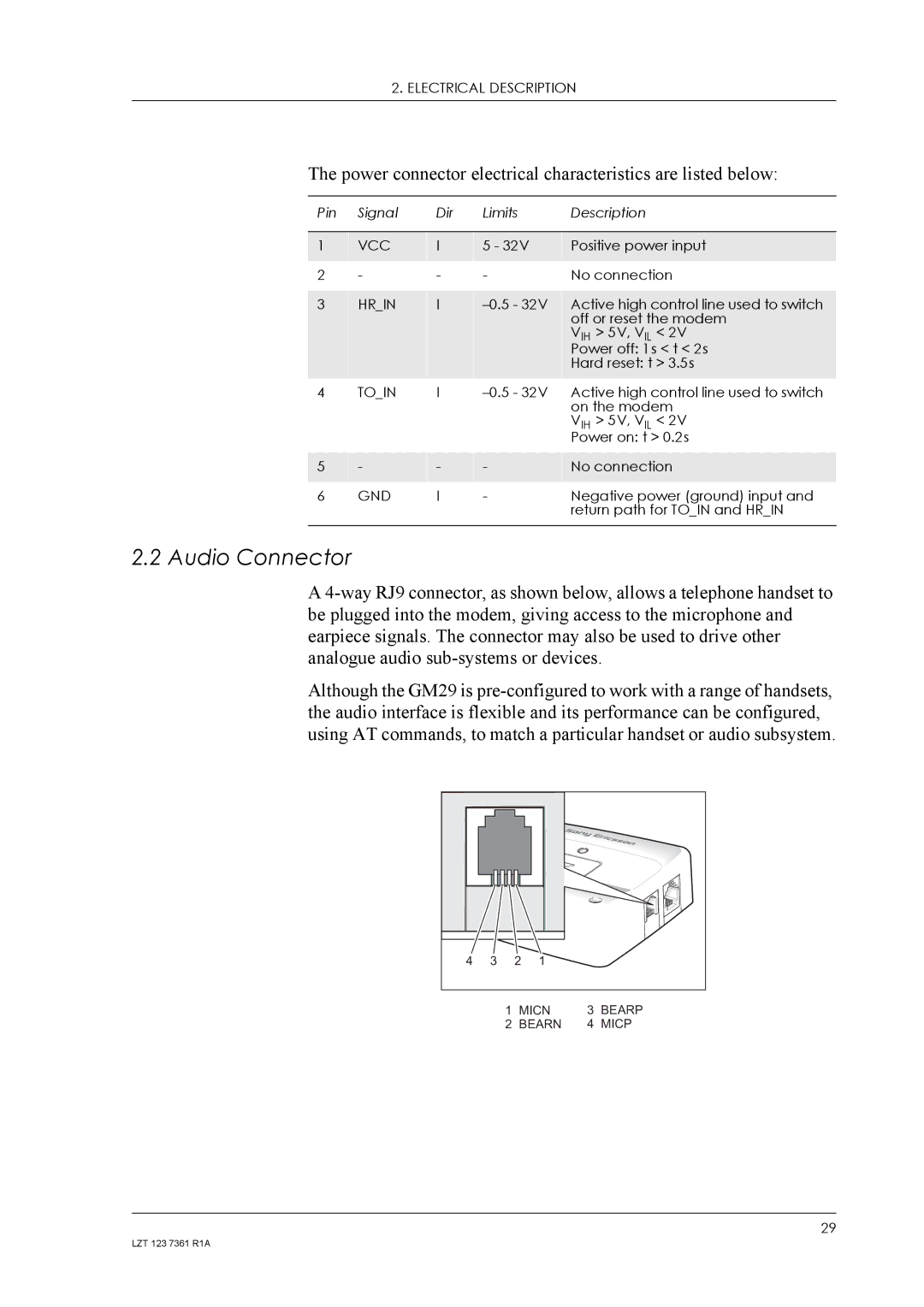
2.2 Audio Connector
A
Although the GM29 is
4 | 3 | 2 | 1 |
1 | MICN | 3 | BEARP |
2 | BEARN | 4 | MICP |
29
LZT 123 7361 R1A
