GM29 INTEGRATOR’S MANUAL
2. Electrical Description
All electrical connections to the GM29 are protected in compliance with the standard air (4kV) and contact (8kV) discharge ESD tests, of EN 301
The modem uses the following industry standard connectors:
•RJ11
•RJ9
•SIM card reader
•FME male coaxial jack (antenna connector)
•
2.1Power Connector
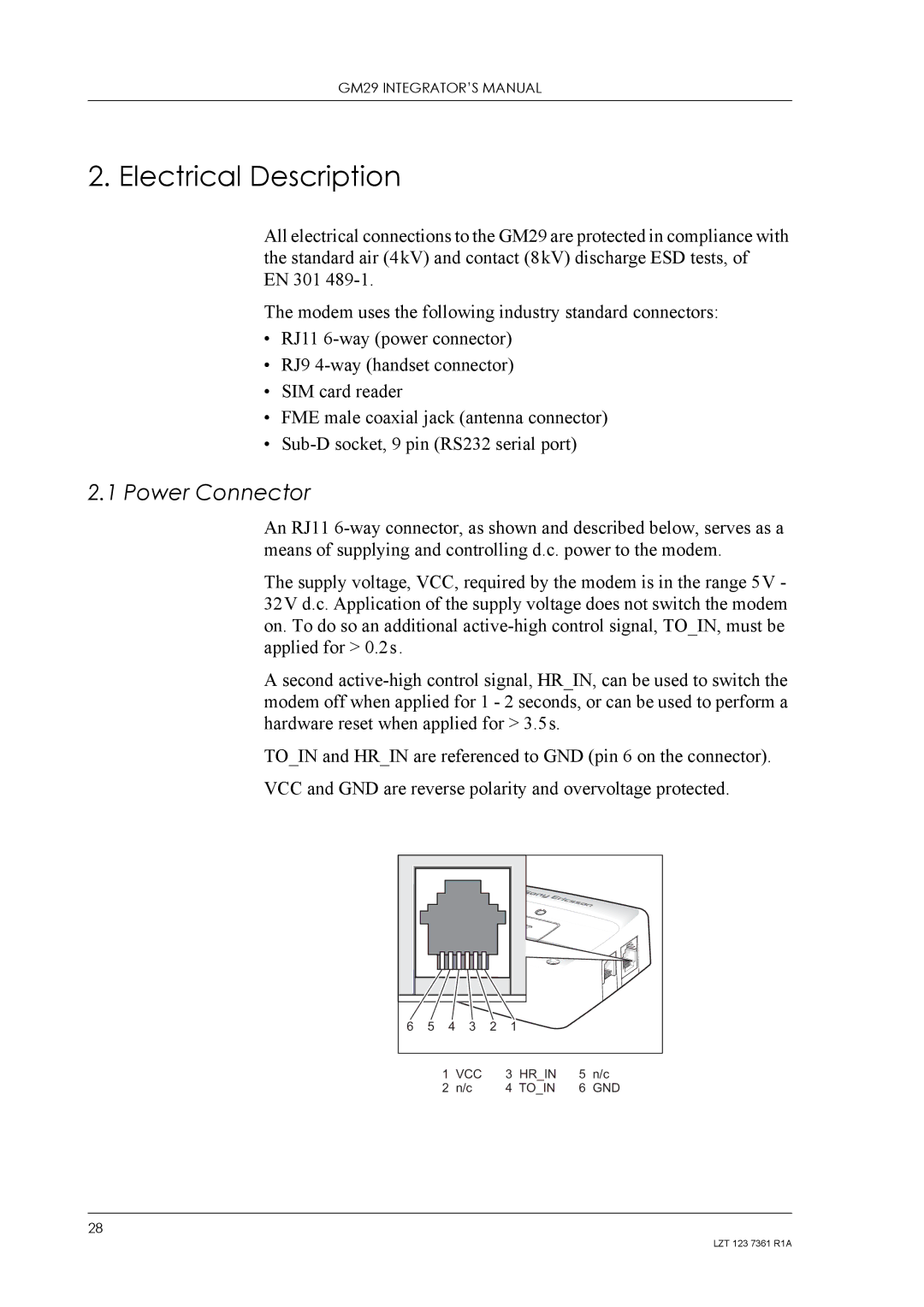
An RJ11
The supply voltage, VCC, required by the modem is in the range 5V - 32V d.c. Application of the supply voltage does not switch the modem on. To do so an additional
A second
TO_IN and HR_IN are referenced to GND (pin 6 on the connector). VCC and GND are reverse polarity and overvoltage protected.
6 | 5 | 4 | 3 | 2 | 1 |
1 | VCC | 3 | HR_IN | 5 | n/c |
2 | n/c | 4 | TO_IN | 6 | GND |
28
LZT 123 7361 R1A