2. ELECTRICAL DESCRIPTION
2.5 RS232 Serial Port
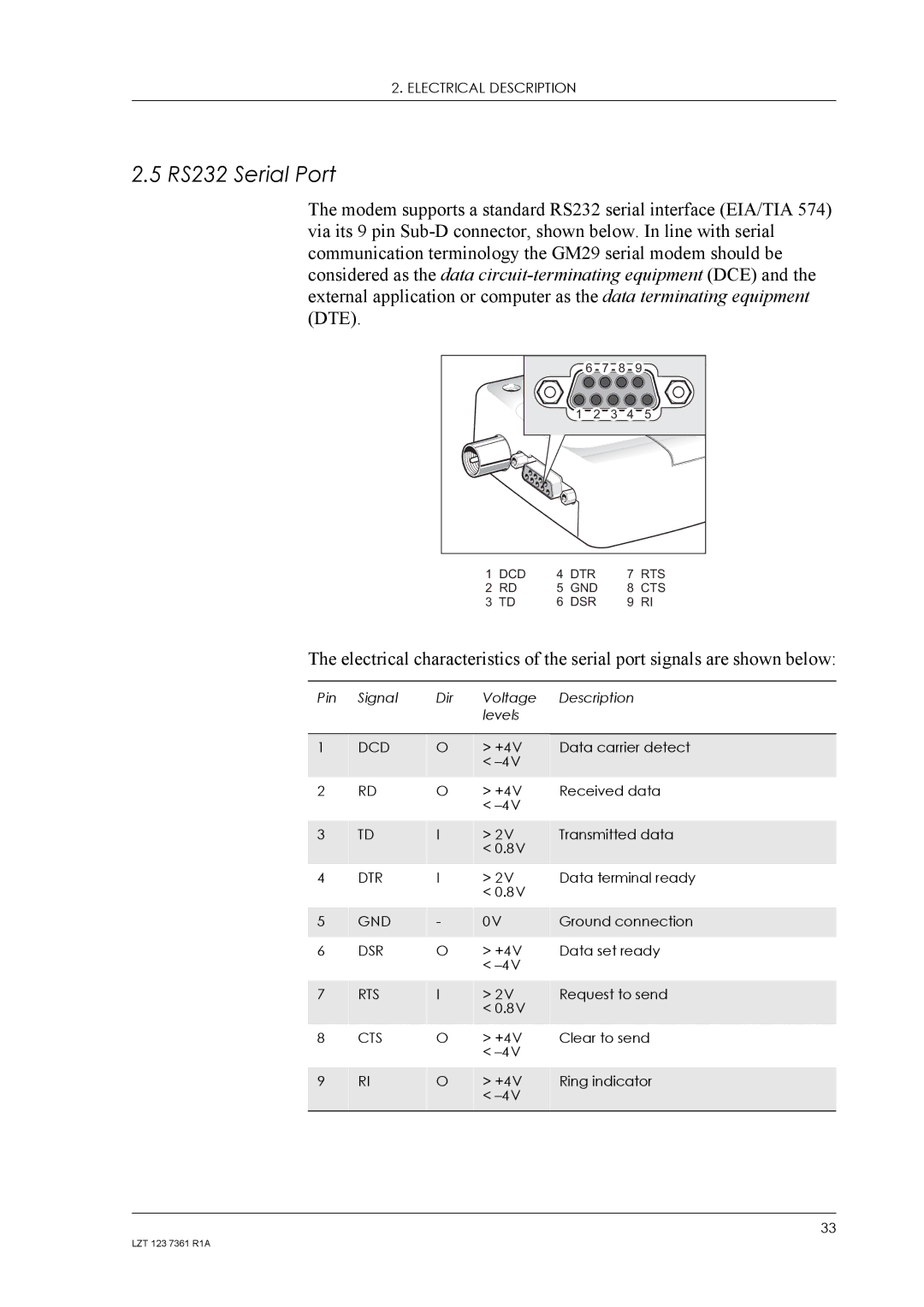
The modem supports a standard RS232 serial interface (EIA/TIA 574) via its 9 pin
6 | 7 |
| 8 | 9 |
1 | 2 | 3 | 4 | 5 |
1 | DCD | 4 | DTR | 7 | RTS |
2 | RD | 5 | GND | 8 | CTS |
3 | TD | 6 | DSR | 9 | RI |
The electrical characteristics of the serial port signals are shown below:
Pin | Signal | Dir | Voltage |
|
|
| levels |
|
|
|
|
1 | DCD | O | > +4V |
|
|
| < |
2 | RD | O | > +4V |
|
|
| < |
3 | TD | I | > 2V |
|
|
| < 0.8V |
4 | DTR | I | > 2V |
|
|
| < 0.8V |
5 | GND | - | 0V |
6 | DSR | O | > +4V |
|
|
| < |
7 | RTS | I | > 2V |
|
|
| < 0.8V |
8 | CTS | O | > +4V |
|
|
| < |
9 | RI | O | > +4V |
|
|
| < |
Description
Data carrier detect
Received data
Transmitted data
Data terminal ready
Ground connection Data set ready
Request to send
Clear to send
Ring indicator
33
LZT 123 7361 R1A