4220 Flow Meter
Section 2 Programming
2.1 Getting Started | You must program the 4220 Flow Meter to accurately monitor a | |||
| flow stream. You must also install the submerged probe level | |||
| sensor. The 4220 will usually also need a primary measuring | |||
| device, a structure placed across a stream that regulates flow. | |||
| This section describes programming the flow meter with the aid | |||
| of the keypad and display. There are nine program steps that | |||
| control all aspects of the flow meter's operation. | |||
| Teledyne Isco ships the flow meter with a program already | |||
| installed that is called the default program. You can use this | |||
| program as an example to see the flow meter's capabilities. Note | |||
| that the default program is just to test the unit at the factory. | |||
| The flow meter's internal computer must always have something | |||
| programmed into the unit, so that becomes the default program. | |||
| Your flow situation will usually require other programming | |||
| choices. The text provided with each screen explains the reasons | |||
| for the various menu options. |
|
| |
2.1.1 Operation of the | The display is a | |||
Display | (LCD). It has a backlight feature for easy viewing in low light sit- | |||
| uations. The display has three different operating modes: | |||
| normal, programming, and messages. In the normal mode, | |||
| the display shows such things as level, flow rate, total flow, | |||
| parameter measurement, etc. In the programming mode, the | |||
| top line of the display shows each step as you work through the | |||
| program while the bottom line shows the choices available for | |||
| that step. In the message mode, the display provides instruc- | |||
| tional information, such as how to leave programming, or what to | |||
| do if you have entered a number that is | |||
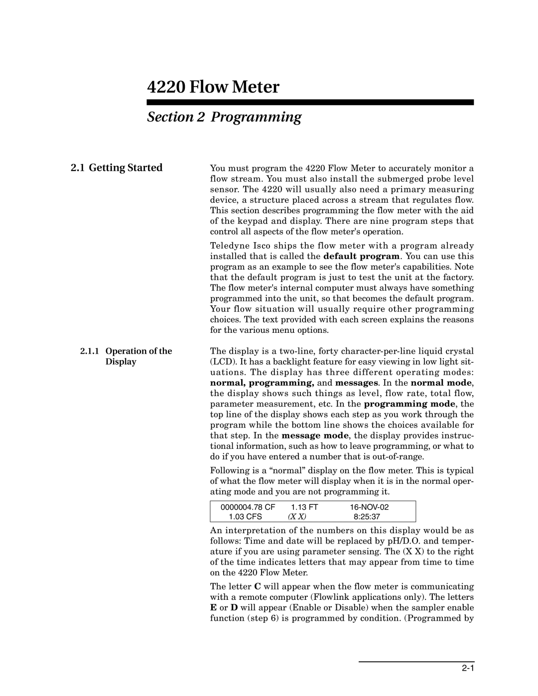
| Following is a “normal” display on the flow meter. This is typical | |||
| of what the flow meter will display when it is in the normal oper- | |||
| ating mode and you are not programming it. | |||
|
|
|
|
|
| 0000004.78 CF | 1.13 FT |
| |
| 1.03 CFS | (X X) | 8:25:37 |
|
An interpretation of the numbers on this display would be as follows: Time and date will be replaced by pH/D.O. and temper- ature if you are using parameter sensing. The (X X) to the right of the time indicates letters that may appear from time to time on the 4220 Flow Meter.
The letter C will appear when the flow meter is communicating with a remote computer (Flowlink applications only). The letters E or D will appear (Enable or Disable) when the sampler enable function (step 6) is programmed by condition. (Programmed by
