4220 Flow Meter
Section 5 Options and Accessories
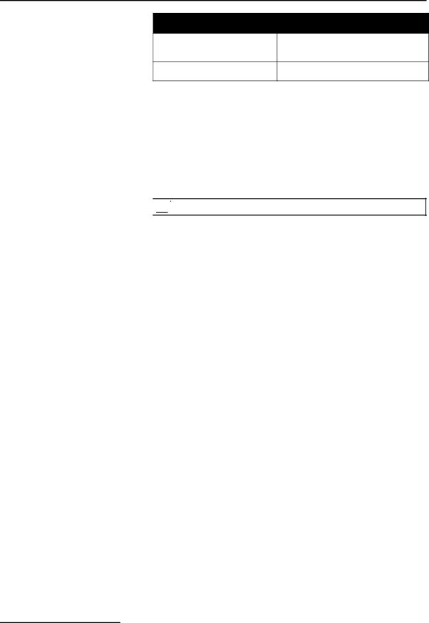
Table 5-1 4-20 mA Output Interface Specifications
Adjustments / Calibration
Maximum Distance
1,500 ft. (457.3 m) using 18 AWG wire.
5.3.2 Internal Multiple | For those needing more than one analog output, Teledyne Isco |
Analog Output Board | offers the Multiple Analog Output Board, which is installed |
| inside the flow meter. This board provides from one to three iso- |
| lated analog outputs. You can order the board with three, two, or |
| one circuit installed. You must specify this when the flow meter |
| is ordered. The board is compatible with the existing external |
| |
| the internal board, the external box, or both, for a maximum |
| number of four analog outputs. |
![]()
![]()
![]()
![]()
![]() Note
Note
If your flow meter has both the multiple analog output board and the external analog converter, the internal ports will be designated Analog Outputs 1, 2, and 3 (depending on how many are present). The external converter will be designated either “External” or “Analog Output 0.”
The Multiple Analog Output Board consumes a minimum of 16 mA per output; consequently, the flow meter should be
•Use a Solar Panel Battery Charger
•Use a larger battery: either a commercial
•Order only one analog output.
•Flow meter program choices also affect power consumption. Use “minimum” settings, if possible. (See Section 1, Table
The outputs from the analog output board are electrically iso- lated from the flow meter and from each other by internal
The analog board terminates in a
