4220 Flow Meter
Section 2 Programming
The level-
SET X
• ADD POINT • • (UNITS) •
Then:
SET 1 DATA POINT 1
ENTER: 0.00 (level units) 0.000 (units of volume)
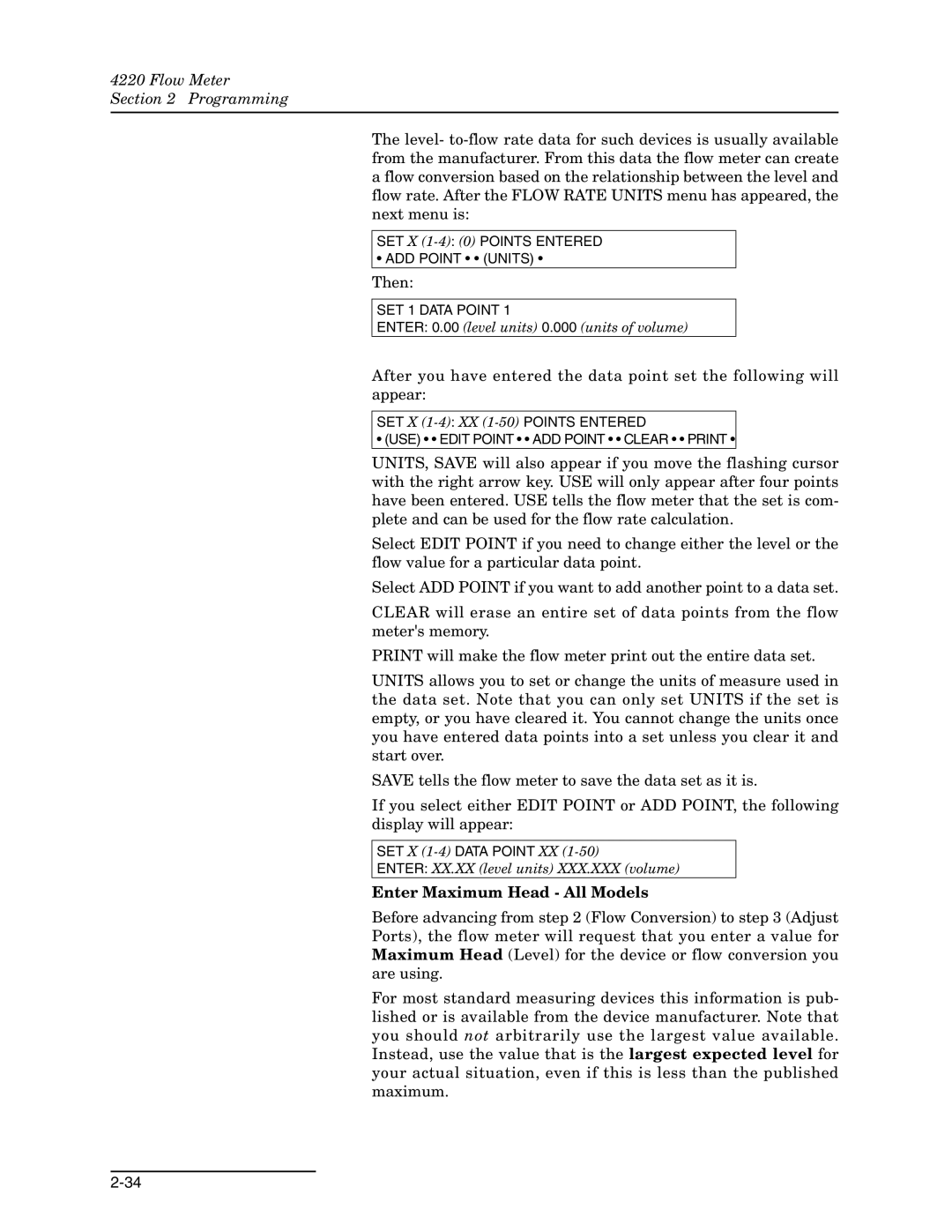
After you have entered the data point set the following will appear:
SET X
• (USE) • • EDIT POINT • • ADD POINT • • CLEAR • • PRINT •
UNITS, SAVE will also appear if you move the flashing cursor with the right arrow key. USE will only appear after four points have been entered. USE tells the flow meter that the set is com- plete and can be used for the flow rate calculation.
Select EDIT POINT if you need to change either the level or the flow value for a particular data point.
Select ADD POINT if you want to add another point to a data set.
CLEAR will erase an entire set of data points from the flow meter's memory.
PRINT will make the flow meter print out the entire data set.
UNITS allows you to set or change the units of measure used in the data set. Note that you can only set UNITS if the set is empty, or you have cleared it. You cannot change the units once you have entered data points into a set unless you clear it and start over.
SAVE tells the flow meter to save the data set as it is.
If you select either EDIT POINT or ADD POINT, the following display will appear:
SET X
ENTER: XX.XX (level units) XXX.XXX (volume)
Enter Maximum Head - All Models
Before advancing from step 2 (Flow Conversion) to step 3 (Adjust Ports), the flow meter will request that you enter a value for Maximum Head (Level) for the device or flow conversion you are using.
For most standard measuring devices this information is pub- lished or is available from the device manufacturer. Note that you should not arbitrarily use the largest value available. Instead, use the value that is the largest expected level for your actual situation, even if this is less than the published maximum.
