www.ti.com | EMAC Functional Architecture |
2EMAC Functional Architecture
This section discusses the architecture and basic function of the EMAC peripheral.
2.1Clock Control
The frequencies for the transmit and receive clocks are fixed by the IEEE 802.3 specification, as shown below:
•2.5 MHz at 10 Mbps
•25 MHz at 100 Mbps
•125 MHz at 1000 Mbps
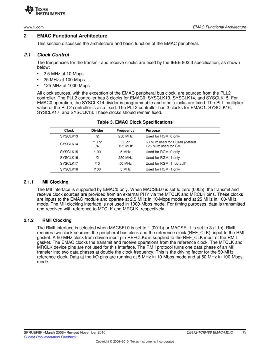
All clock sources, with the exception of the EMAC peripheral bus clock, are sourced from the PLL2 controller. The PLL2 controller has 3 clocks for EMAC0: SYSCLK13, SYSCLK14, and SYSCLK15. For EMAC0 operation, the SYSCLK14 divider is programmable and other clocks are fixed. The PLL multiplier value of the PLL2 controller is also fixed. The PLL2 controller has 3 clocks for EMAC1: SYSCLK16, SYSCLK17, and SYSCLK18. These clocks should remain fixed.
Table 3. EMAC Clock Specifications
Clock | Divider | Frequency | Purpose | |
SYSCLK13 | /2 | 250 MHz | Used for RGMII0 only | |
SYSCLK14 | /10 or | 50 or | 50 MHz used for RGMII (default | |
/4 | 125 MHz | 125 MHz used for GMII | ||
| ||||
SYSCLK15 | /100 | 5 MHz | Used for RGMII0 only | |
SYSCLK16 | /2 | 250 MHz | Used for RGMII1 only | |
SYSCLK17 | /10 | 50 MHz | Used for RGMII1 (default) | |
SYSCLK18 | /100 | 5 MHz | Used for RGMII1 only | |
|
|
|
|
2.1.1MII Clocking
The MII interface is supported by EMAC0 only. When MACSEL0 is set to zero (000b), the transmit and receive clock sources are provided from an external PHY via the MTCLK and MRCLK pins. These clocks are inputs to the EMAC module and operate at 2.5 MHz in
2.1.2RMII Clocking
The RMII interface is selected when MACSEL0 is set to 1 (001b) or MACSEL1 is set to 3 (11b). RMII requires two clock sources, the peripheral bus clock and the reference clock (REF_CLK), input to the RMII gasket. A
SPRUEF8F | C6472/TCI6486 EMAC/MDIO | 15 |
Submit Documentation Feedback |
|
|
Copyright ©
