MDIO Registers | www.ti.com |
4.15 MDIO User PHY Select Register 1 (USERPHYSEL1)
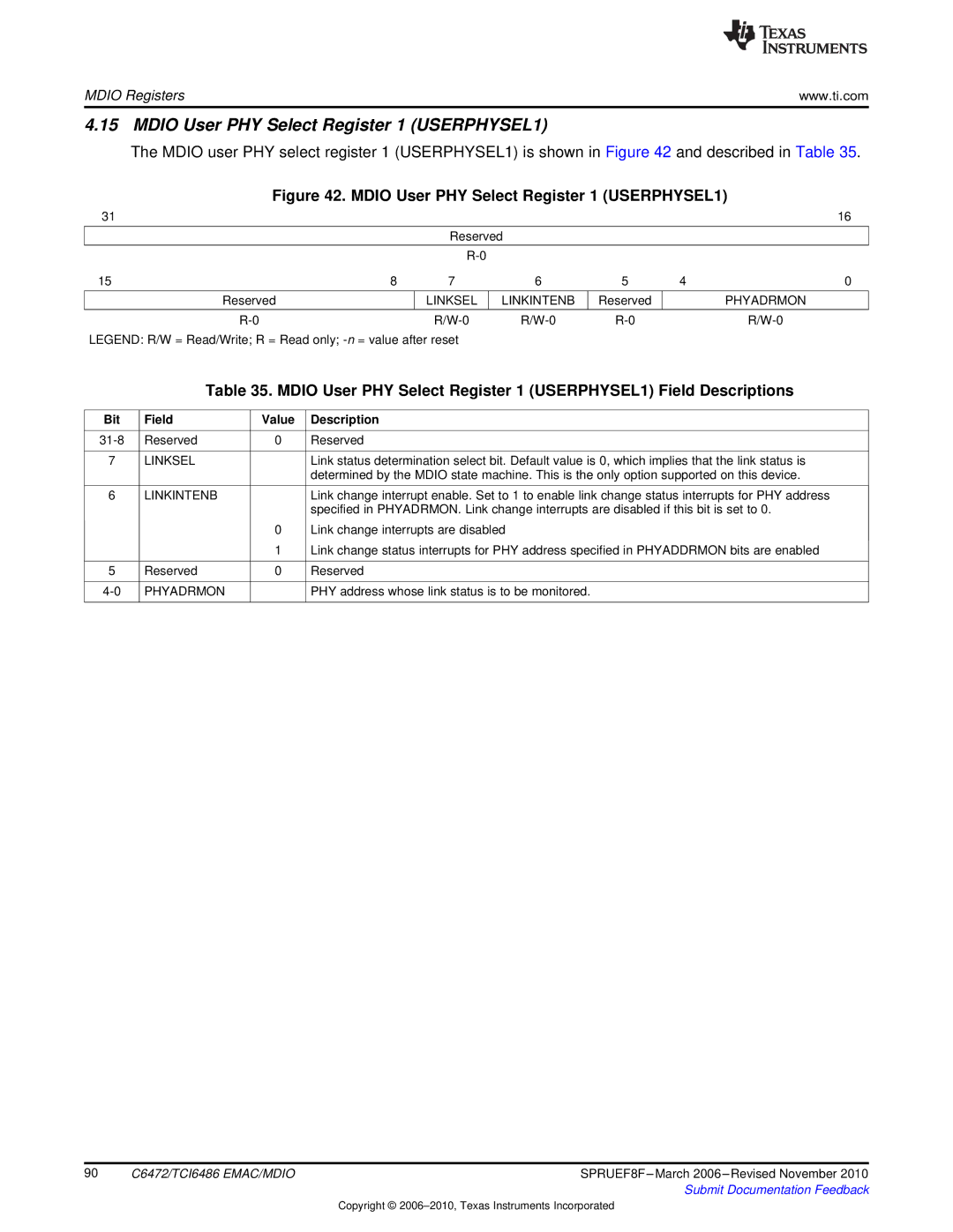
The MDIO user PHY select register 1 (USERPHYSEL1) is shown in Figure 42 and described in Table 35.
Figure 42. MDIO User PHY Select Register 1 (USERPHYSEL1)
31 |
|
|
|
|
| 16 |
|
| Reserved |
|
|
| |
|
|
|
|
|
|
|
|
|
|
|
|
| |
15 | 8 | 7 | 6 | 5 | 4 | 0 |
|
|
|
|
|
|
|
Reserved |
| LINKSEL | LINKINTENB | Reserved |
| PHYADRMON |
|
|
|
|
|
|
|
|
| |||||
LEGEND: R/W = Read/Write; R = Read only;
Table 35. MDIO User PHY Select Register 1 (USERPHYSEL1) Field Descriptions
Bit | Field | Value | Description |
|
|
|
|
Reserved | 0 | Reserved | |
|
|
|
|
7 | LINKSEL |
| Link status determination select bit. Default value is 0, which implies that the link status is |
|
|
| determined by the MDIO state machine. This is the only option supported on this device. |
|
|
|
|
6 | LINKINTENB |
| Link change interrupt enable. Set to 1 to enable link change status interrupts for PHY address |
|
|
| specified in PHYADRMON. Link change interrupts are disabled if this bit is set to 0. |
|
| 0 | Link change interrupts are disabled |
|
| 1 | Link change status interrupts for PHY address specified in PHYADDRMON bits are enabled |
|
|
|
|
5 | Reserved | 0 | Reserved |
|
|
|
|
PHYADRMON |
| PHY address whose link status is to be monitored. | |
|
|
|
|
90 | C6472/TCI6486 EMAC/MDIO | SPRUEF8F |
|
| Submit Documentation Feedback |
Copyright ©