www.ti.comEMAC Functional Architecture
Table 8. EMAC and MDIO Signals for RMII Interface (continued)
Signal Name | I/O | Description |
RMRXER | I | Receive error (RMRXER). The receive error signal is asserted for one or more reference clock |
|
| periods to indicate that an error was detected in the received frame. This is meaningful only during |
|
| data reception when RMCRSDV is active. It is driven synchronously to the RMII reference clock. |
MDCLK | O | Management data clock (MDCLK). The MDIO data clock is sourced by the MDIO module on the |
|
| system. It is used to synchronize MDIO data access operations done on the MDIO pin. The |
|
| frequency of this clock is controlled by the CLKDIV bits in the MDIO control register (CONTROL). |
MDIO | I/O | Management data input output (MDIO). The MDIO pin drives PHY management data into and out of |
|
| the PHY by way of an access frame consisting of start of frame, read/write indication, PHY address, |
|
| register address, and data bit cycles. The MDIO pin acts as an output for everything except the data |
|
| bit cycles, when the pin acts as an input for read operations. |
|
|
|
The
On the TCI6486/C6472 device, RMII pins are multiplexed with other
If the device is interfaced to an Ethernet switch through the RMII interface, all device RMII reference clocks should be externally sourced from the same
2.3.3Gigabit Media Independent Interface (GMII) Connections
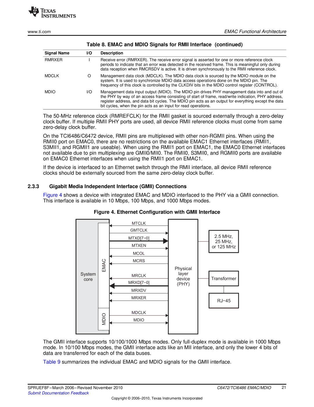
Figure 4 shows a device with integrated EMAC and MDIO interfaced to the PHY via a GMII connection. This interface is available in 10 Mbps, 100 Mbps, and 1000 Mbps modes.
Figure 4. Ethernet Configuration with GMII Interface
System
core
EMAC
MDIO
MTCLK
GMTCLK
MTXD[7−0]
MTXEN
MCOL
MCRS
MRCLK
MRXD[7−0]
MRXDV
MRXER
MDCLK
MDIO
Physical
layer
device (PHY)
2.5MHz,
25 MHz,
or 125 MHz
Transformer
RJ−45
The GMII interface supports 10/100/1000 Mbps modes. Only
Table 9 summarizes the individual EMAC and MDIO signals for the GMII interface.
SPRUEF8F | C6472/TCI6486 EMAC/MDIO | 21 |
Submit Documentation Feedback |
|
|
Copyright ©