Advanced Energy®
Host Port—DeviceNet
This section describes the DeviceNet Host port interface. To determine if your Apex unit has this interface, use the PIN from your Apex unit and the following Configuration Note.
This section of the manual provides information for the:
DeviceNet option
PIN position 6, (A 1 2 3 4 5 6 7 8 9 10 11 12 13 14 15 16 17) option 2. (When identifying the PIN position, remember that the A at the beginning of the PIN is not counted as a position. The PIN option is the number or letter you should look for in the specified position.)
For more information about the PIN and for a complete list of how PIN positions correspond to Apex product options, see Table
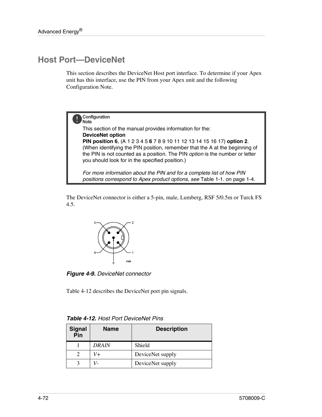
The DeviceNet connector is either a
Figure 4-9. DeviceNet connector
Table
Table
Signal | Name | Description |
Pin |
|
|
|
|
|
1 | DRAIN | Shield |
|
|
|
2 | V+ | DeviceNet supply |
|
|
|
3 | V- | DeviceNet supply |
|
|
|